Electronic Dice (Part 1)

This is about as simple an Arduino project as you can build that still has a real-world use. If you’re comfortable with getting the ‘Blink’ sketch running, then you should have no problem with constructing this electronic dice. If, however, you’re an Arduino master looking to learn about Arizona Microchip’s PIC microcontrollers, then read on, as in part 2 I’ll be implementing the same functionality with a circuit based around a PIC 12F629 coded in assembler.

The circuit is pretty simple; a simple push-button is pressed to “throw” the dice, and the result is displayed as a familiar dot-pattern for a few seconds before turning off to wait for the next throw. The “randomness” is in generated by having a counter that continuously loops through the values 1 to 6 very quickly until a button is pressed. The moment the button is pressed the counter is stopped and its value is displayed as a dice dot-pattern.

Hardware

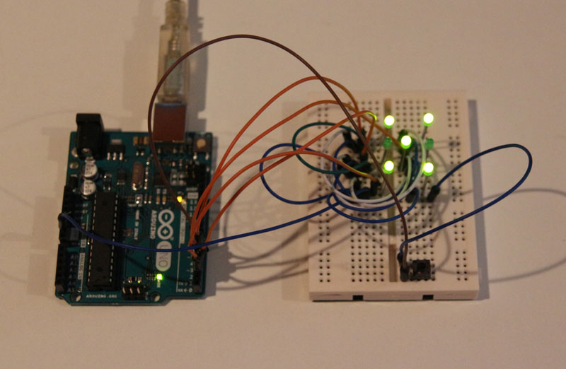
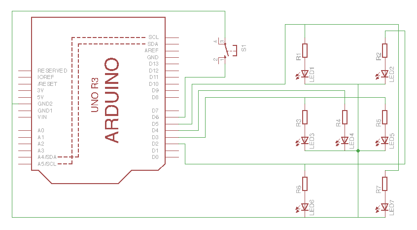
In addition to an Arduino (I’ve used an UNO R3), you’ll need a push-button switch and seven LEDs with appropriate current limiting resistors (or you could do what I did and use LEDs with built in resistors to save some complication).

Arduino Dice Schematic
Software

Much like the hardware, the software sketch is nice and simple:

// Arduino Dice
// Simon Buckwell
// July 2015

// variables
int d = 0; // dice value

void setup()
{
  // set up GPIO pins
  pinMode(2, OUTPUT); // GPIO 2 - controls LED2 and LED6
  pinMode(3, OUTPUT); // GPIO 3 - controls LED3 and LED5
  pinMode(4, OUTPUT); // GPIO 4 - controls LED4
  pinMode(5, OUTPUT); // GPIO 5 - controls LED1 and LED7
  pinMode(6, INPUT_PULLUP); // GPIO 6 - detects push-button
}

void loop()
{
  // turn all LEDs off
  digitalWrite(2, LOW);
  digitalWrite(3, LOW);
  digitalWrite(4, LOW);
  digitalWrite(5, LOW);

  // loop through values 1 to 6 until the push-button is pressed
  do
  {
    d = d % 6;
    d++;
  } while (digitalRead(6) == HIGH);

  // display value as dot-pattern
  if (d == 1)
  {
    // dot-pattern for 1 - turn on LED4
    digitalWrite(4, HIGH);
  }
  else if (d == 2)
  {
    // dot-pattern for 2 - turn on LED2 and LED6
    digitalWrite(2, HIGH);
  }
  else if (d == 3)
  {
    // dot-pattern for 3 - turn on LED2, LED4 and LED6
    digitalWrite(2, HIGH);
    digitalWrite(4, HIGH);
  }
  else if (d == 4)
  {
    // dot-pattern for 4 - turn on LED1, LED2, LED6 and LED7
    digitalWrite(2, HIGH);
    digitalWrite(5, HIGH);
  }
  else if (d == 5)
  {
    // dot pattern for 5 - turn on LED1, LED2, LED4, LED6 and LED7
    digitalWrite(2, HIGH);
    digitalWrite(4, HIGH);
    digitalWrite(5, HIGH);
  }
  else
  {
    // dot-pattern for 6 - turn on LED1, LED2, LED3, LED5, LED6 and LED7
    digitalWrite(2, HIGH);
    digitalWrite(3, HIGH);
    digitalWrite(5, HIGH);
  }

  // wait 3 seconds
  delay(3000);
}
dice_arduino_proto
Arduino dice on prototyping board

R/C Camera Truck

This project was all kinds of wrong; over engineered and built on untested assumptions. It subsequently took stupidly longer that it ought to.

The plan was to finally do something with the R/C truck that my nephew let me have after a clear-out and the wireless camera I bought off eBay many years ago “because it was cool”. This is the circuit I cam up with:

The 100R resistors connected in parallel (resulting in a combined 33R resistance) together with the 2200uF capacitor would filter out power noise from the battery (the battery also powers the truck’s drive motor and servo) before it got to the (rather excellent) Pololu 9V Step-up/down voltage regulator that would provide power to the camera/transmitter unit. The LEDs being driven through the four resistors would provide light so the operator could see where they were driving when it was dark. So far, so reasonable.

Well, rather than doing some experiments and testing the my assumptions I just started to build. Bad idea.

For a start, I discovered that the 100R resistors limited the current enough that when the camera was powered there wasn’t enough current the light the LEDs. I solved this by removing the resistors from the circuit by bypassing them with a patch wire – problem solved; the camera and lights could both operate together.

Secondly, when testing the truck in the dark it became apparent that while the now working headlights looked very cool, they didn’t really provide any meaningful amount of illumination!

Mostly unnecessary
Mostly unnecessary

It turns out that the following circuit was really the one I should’ve built (but not before testing it, obviously!):

Simple is efficient
Simple is efficient

Not only is the circuit simpler, but rather than having to construct a board and drill-out/mount a box, I could’ve just soldered everything together, wrapped it all in insulation tape and fixed it to the truck with cable-ties: Job done.

Always remember: “If you haven’t tested it, it doesn’t work

Completed Truck
Completed Truck

I’d hoped to embed a video of the view from the truck driving, but just as I’d finally go the thing working the receiver decided to go kaput. I’ve got another one on the way from China, so I hopefully I’ll be able to do that soon.

Amiga 600

My Amiga 600 was a car-boot sale find about 10 years ago. In an time when the Playstation 2 was past its peak I managed to buy it for £5. It came with loads of disks, PSU and a couple of joysticks.

Amiga 600
Amiga 600

After testing it to confirm it worked I’m ashamed to say that it simply got put back in a box and consigned to my loft for the next decade…

Well, as part of my on-going project to ensure that my old tech is more usable I decided to resurrect it. First things first – did it still work? Fortunately, I not only have an old-but-good Panasonic Quintrix CRT TV, but I also hung onto my Amiga to SCART cable. This is not as trivial as it sounds. Many older games consoles and computers used standard connectors for their various interfaces that are still common today, but the Amiga’s monitor port used a 23 pin ‘D’ connector. These are all-but impossible to find nowadays. It’s possible to buy Amiga monitor cables, but most of them use the common 25 pin ‘D’ with two of the outer pins cut off – it works, but it’s hardly elegant.

Amiga RGB SCART cable with very hard to come by genuine 23 pin 'D' connector
Amiga RGB SCART cable with very hard to come by genuine 23 pin ‘D’ connector

I plugged everything in, flipped the power switch, and was greeted with the boot screen.

A600 boot screen - it still works
A600 boot screen – it still works

The good news was that it still worked, the bad news was that it only had the 37.299 ROM installed rather than the final 37.350 required for booting from a hard drive above 40MB.

37.299 ROM
37.299 ROM

The Amiga still has quite an active community of enthusiasts, so getting hold of a new 37.350 ROM wasn’t a problem. It is also no longer necessary to use an actual hard disk drive, as its possible to use a relatively simple and inexpensive Compact Flash card adapter instead. I purchased the ROM, CF adapter and CF card from amigkit.com. The CF card came pre-loaded with auto-booting software to install the Workbench, etc. on the card.

Kickstart 37.350
Kickstart 37.350
Compact Flash to 44 pin IDE adapter

Time to breakout the toolbox to get at the motherboard.

A600 motherboard
A600 motherboard

Replacing the Kickstart ROM is fairly straightforward, but there are a couple of gotchas. If you’re not used to dealing with ICs then know that they usually come with their pins splayed-out a bit, but to use them the pins have to point straight down. There are two mains ways of doing this – using a pin straightening tool, or carefully bending the pins against a flat surface (usually a desk) one row at a time. If you’re going to be doing this procedure a lot, then do yourself a favour and get the proper tool. They’re not expensive, get the job done reliably, and are far quicker to use.

Pin straightening tool

The next gotcha results from a rather bizarre decision made by the designers of the A600 motherboard – while the Kickstart IC has (a very standard) 40 pins, the IC socket on the motherboard has 42 pins (I didn’t even know 42 pin sockets existed!). If, like me, you plug the IC into the socket incorrectly then not only will the Amiga not boot up, but the new Kickstart IC will start to get very hot indeed! I realised what had happened before the IC caused itself or the Amiga irreparable damage. The photo shows the correct orientation and alignment the IC on the motherboard of my A600 – board layouts and specs can change between revisions, however, so if you’re going to do this yourself then the best way of determining the correct way of inserting the new IC is to take careful note of how the original one is oriented/aligned.

New Kickstart ROM inserted into socket

Installing the new Kickstart IC (correctly!) yields the following on the boot screen:

37.350 ROM
37.350 ROM

Time to install the CF adapter, which is connected where the hard-drive would’ve been connected. Make sure you push hard enough to make a proper connection – when being extra careful with vintage hardware it’s easy to convince yourself (as I did) that the connector is seated properly (when it needs a bit more of a shove!).

CF card acting as HDD

Booting up takes you straight into the Workbench install utility that was pre-installed on the CF card – have your system disks ready and just follow the instructions.

Installing Workbench on "HDD" (CF card)
Installing Workbench on “HDD” (CF card)

Right, that’s the A600 up and running properly, now whatever happened to my A1200?

Ah yes – that is going to be a bit trickier:

Amiga A1200 (Err, in "kit" form)
Amiga A1200 (Err, in “kit” form)

To be continued…

VIC 20 Resurrection

In the quest for subjects for blog posts I think this is somewhat “low hanging fruit”.

Boxed VIC20
Boxed VIC20

I finally got round to retrieving my old Commodore VIC20 from my parents house. It was a present from my parents on my 14th birthday in July 1982 and changed my life. Still boxed and in pretty good condition, I was pretty confident about it still being in working order – despite having not been powered up for around 30 years.

VIC20
VIC20

After fitting a new plug I connected the power supply and switched it on – the red power LED fired up and no burning-smell/excess-heat was produced! On to try to get a picture from a television…

To display a picture on a TV usually involved plugging in the VIC20 to the aerial socket of the TV via the included RF modulator. The picture and sound produced by this horrible thing was pretty atrocious most of the time; the VIC20 does output video and audio directly, but most TVs back in the early 80s didn’t have direct inputs. Things are different now, of course, so it was off to the workshop to make up an AV cable.

Most hated and reviled RF modulator

To make an AV cable for a VIC20 you’ll need:

  • a 5 pin DIN plug with the pins arranged in a 180 degree pattern
  • a composite video cable
  • an audio cable
  • soldering iron + basic tools

First, make up the video cable so that you have the phono plug on one end and stripped back inner core and shield on the other. Do the same for the audio cable.

Video and audio cables
Stripped video and audio cables

Solder the outer shields of both the video and audio cables to the GND pin, the video to the Video pin, and the audio to the Audio pin (Duh!):

VIC20 AV DIN plug
VIC20 AV DIN plug

Re-assemble the plug housing (you did remember to thread the DIN plug boot onto the cables before soldering right?!) and give it a try.

Success!
Success!

Right, now where is that copy of Amok

In the beginning…

It was supposed to be a simple fix, something trivial to kick the blog off with. Re-soldering one-or-two dry joints and a bit of clean up, I figured.

Commodore Calculator (c. Late 1970s)

I found my old Commodore calculator in one of the (many) boxes of old tech in my loft. It was given to me as a birthday present by my grandparents in July 1979, and was the first digital device I owned. I was keen to start using it again, but I seemed to recall that it had developed a problem with the display. Sure enough, powering it up revealed that the upper-right segment of the least significant digit was dead.

That last digit should be an '8'
That last digit should be an ‘8’

Ok then, out with the screwdriver to see what lies within:

Simple circuit board, coarse soldering, cat hair.

Yes, during initial inspection I discovered several fine hairs that almost certainly originated from my long departed cat, Tom. Quite how they managed to work their way in I have no idea (one was actually under the display lens cover!)

Tom - despite appearances to the contrary - one of the smartest cats who ever lived.
Tom – despite appearances to the contrary – one of the smartest cats who ever lived.

Folding back the main (err, only) board to revealed the display, and the realisation that this wasn’t going to be the easy fixed I’d hoped, if possible at all.

Yes - back in the 70s even simple calculators had DC input jacks!
Yes – back in the 70s even simple calculators had DC input jacks!

It occurred to me that it wasn’t going to be a simple dry-joint re-soldering job. The individual digits in the display were multiplexed, so a simple bad connection between the display and the main board would’ve manifested itself as something like either a whole digit or the same segment in all digits being dead.

Display lens cover (just how did a cat hair work its was underneath?)
Display lens cover (just how did a cat hair work its way underneath?)

Prizing off the lens cover caused my heart to sink – the digits were absolutely tiny, and were connected to the PCB by wires finer than a human (and cat) hair:

segments_exposedI quickly located the source of the problem – the track in the place where the dead segment was connected was very corroded:

Corrosion - in worst place.
Corrosion – in the worst place.

Well, using a soldering iron was totally out of the question, so I called it a day and hoped a solution would present itself. I have a rule when it comes to faulty old tech, I call it the rule of Three ‘R’s: Repair, Repurpose, or Rubbish. I’d hate to have to junk the thing for such a simple defect. There had to be a way.

The answer came to me using technique I’ve honed over many years of mental training – I give in and go and do the washing-up/re-arrange the fridge/vacuum the lounge/etc.

Electrically conductive silver paint instead of solder turned out to be the answer, there’d be no heat and I could apply it with a fine point. If you’re in the UK then Maplin sell it (http://www.maplin.co.uk/p/electrically-conductive-silver-paint-n36ba) – its the same stuff that you use to repair broken tracks in heated rear car windows.

To be honest, applying it with a cocktail stick while wearing a pair of glasses plus double jeweller’s loupes wasn’t ideal and resulted in a blob across several tracks. Once it had dried I managed to scrape away the parts of the paint that would’ve caused unwanted shorts, and by some miracle it actually worked. I think it was just as much luck as judgement, but, hey, it all counts!

Back in business!
Back in business!