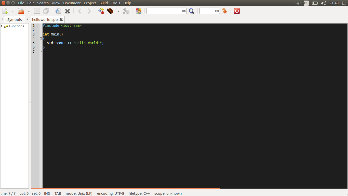
When you fire-up your modern IDE, chances are that there is a vertical line running down the text editing area:
Do you know why this line it there? Well, this line marks the 80th column of text, which many coding standards define as the longest that a single line of code should be before wrapping onto the next line. Give yourself +1 points if you thinks that’s why the 80th columns marker is displayed.
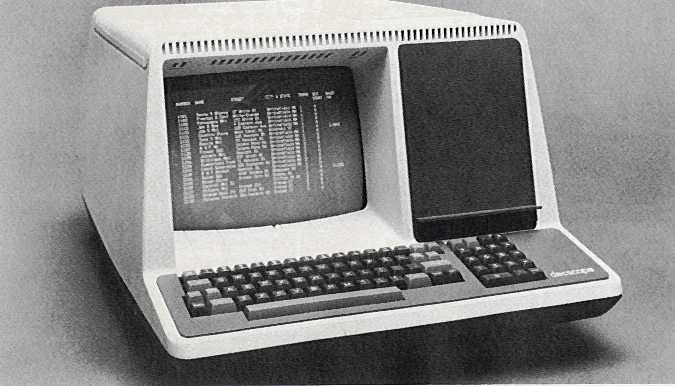
OK, but why 80 columns in particular? If you then say “But Simon, that’s because old computer terminals could only display 80 columns”, then give yourself another +1 points:
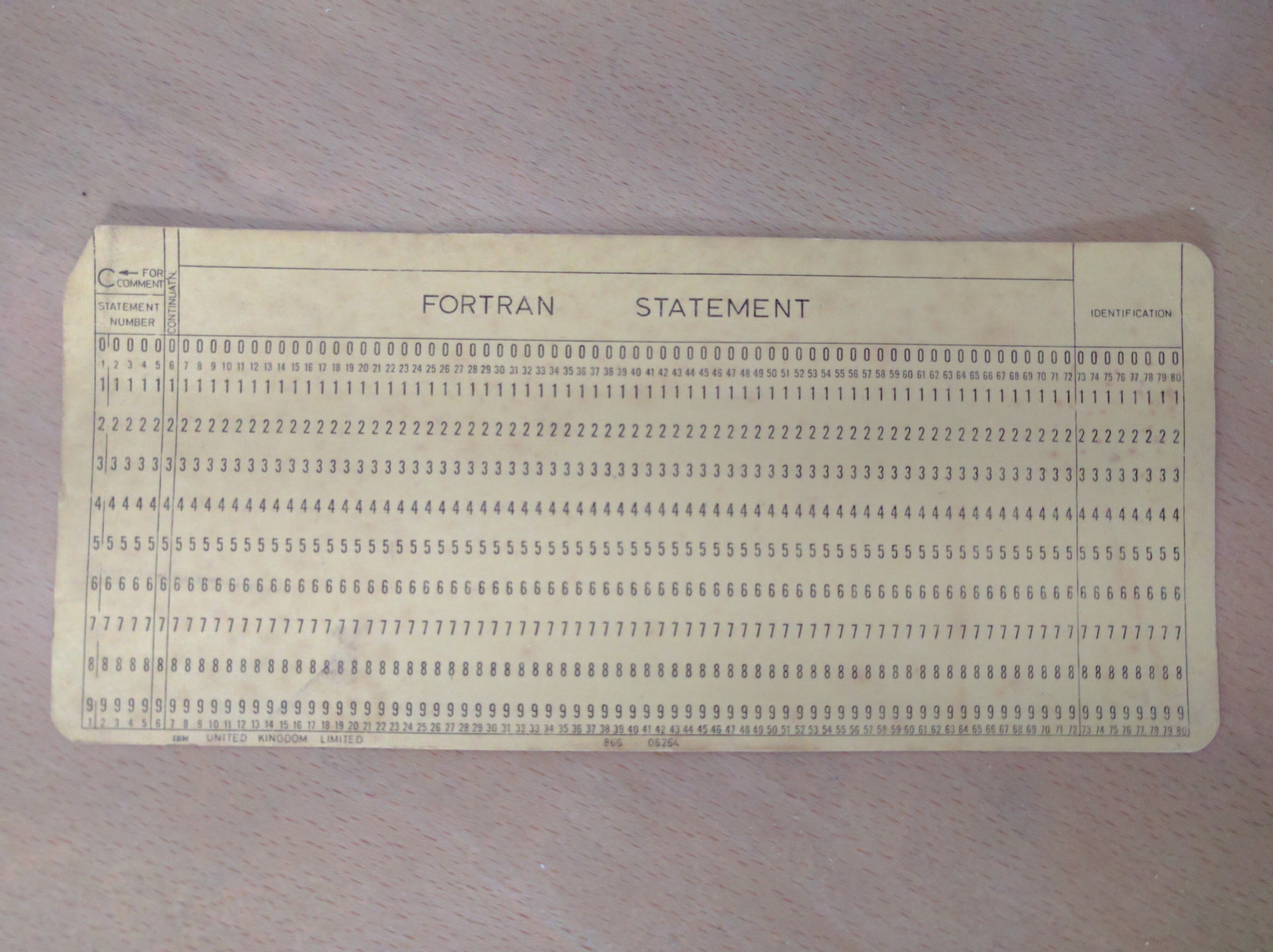
The IBM punched card was used in the 1950s and 1960s by IBM and others to store data and code for processing by computer. The 80 column punched card predates even this, however – IBM designed the format in 1928 for storing numerical data for processing using semi-automatic electromechanical data processing equipment.
So, your modern IDE has a feature that relates to design decision made in the 1920s.
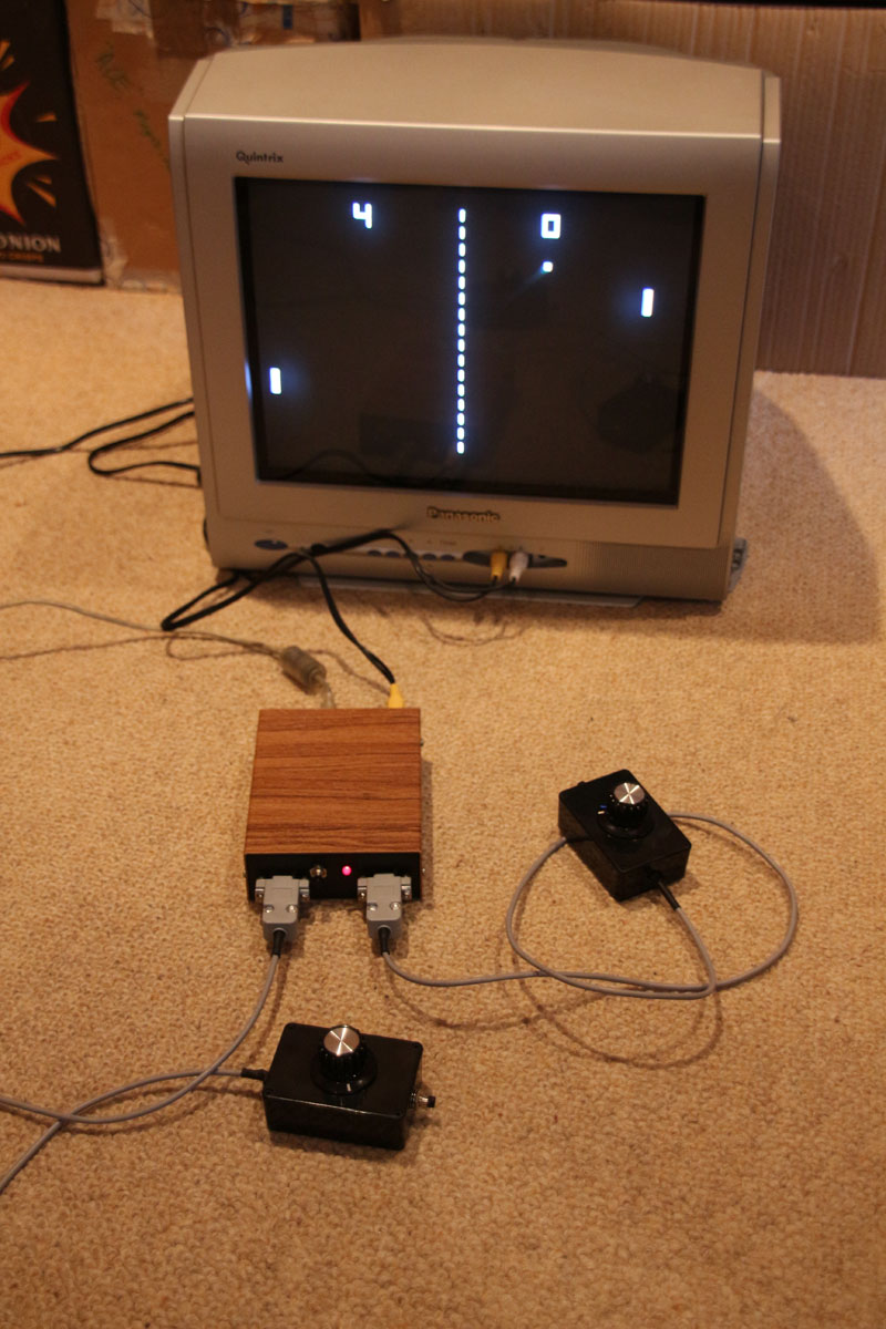
I always wanted to build my own games console, so I was pleased when I stumbled across the TVOut library for the Arduino. It enables many different types of Arduino to generate both video (PAL and NTSC) and audio signals using interrupts. One of the best things about the library is the minimal hardware that is required to implement it – just 2 resistors at its most basic.
Of course, I wasn’t surprised to find out that others had had the same idea, probably the best known of which is the Hackvision by nootropic design.
I wanted to build a system that allowed the external connection of 2 joystick or 2 paddle controllers, and the Hackvision *almost* meets these requirements; 2 paddles can be used, but it only allows for 1 joystick/d-pad. Now I could’ve just ignored the Hackvision, and built my own version, but the Hackvision has had some really good games written for it I wanted to be able to play. I needed a way to build something that could be used with 2 joysticks, but was still compatible with the Hackvision.
The Hackvision design does actually have unassigned IO pins, although not the 5 required to simply assign to the functions of a joystick. I found that I could *just* manage to connect everything if I reused pin D0 (which is used for the first paddle button) for a direction function on the second joystick, and used pin D1 for both the paddle button and joystick button on the second controllers (the first controllers use different pins for the paddle and joystick buttons).
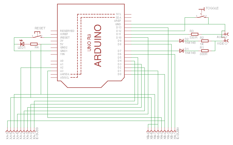
Confused?! The circuit and pinout should make things clearer:
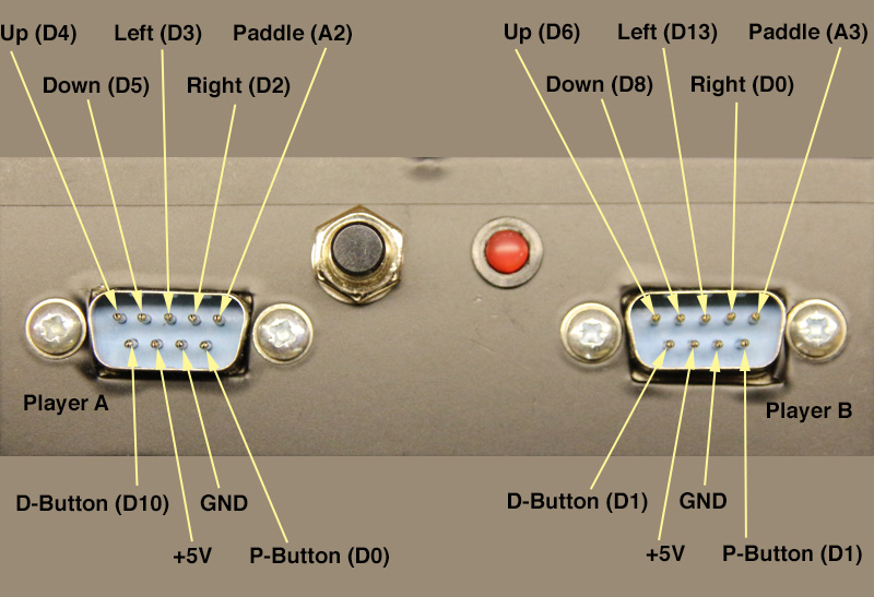
Console circuit – basically an Arduino and a hand-full of passive components.Controller ports labelled with functions and associated Arduino pins
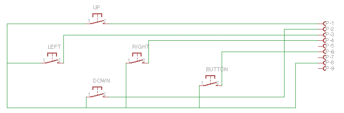
Sticking to the pinouts for Player A & B ports enables the use of classic joysticks with an “Atari” connector that were used throughout the 80s and 90s, and can still be sourced relatively easily on eBay, etc. If you really insist on making your own, then this is the circuit:
Joystick/D-Pad circuit
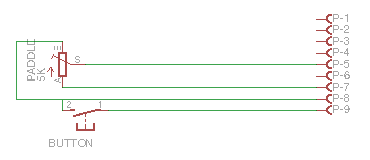
I’m afraid you’ll have to make your own paddle controllers, but they’re pretty simple:
Paddle circuitPaddle controller construction
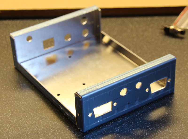
Housing a project in an enclosure is always more complicated and time consuming that you anticipate. I happened to have an aluminium project box in my parts-bin:
Prepared aluminium chassis
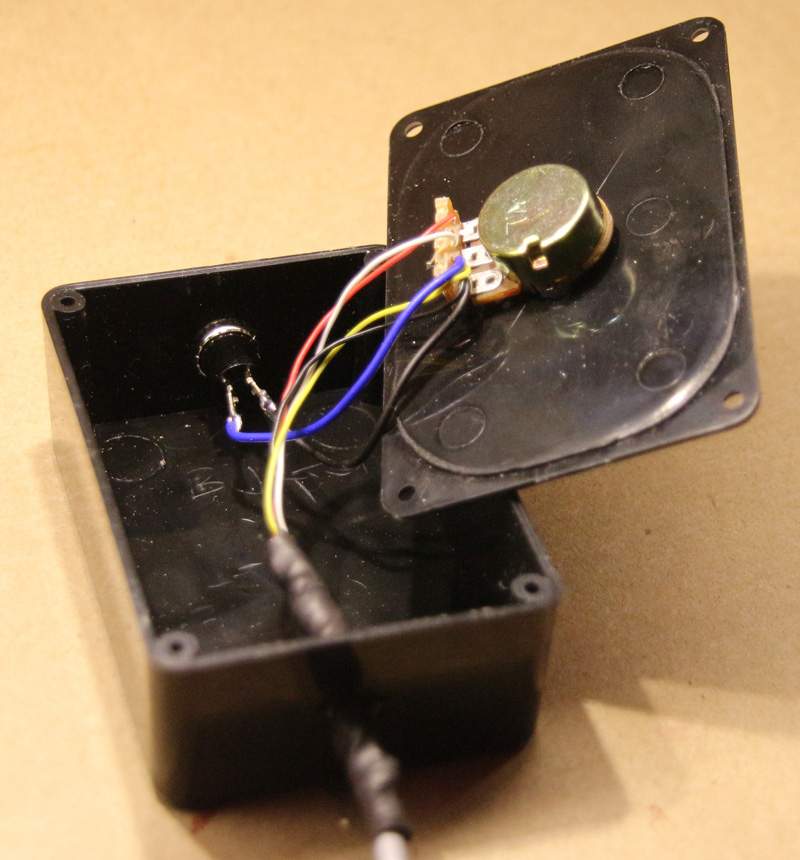
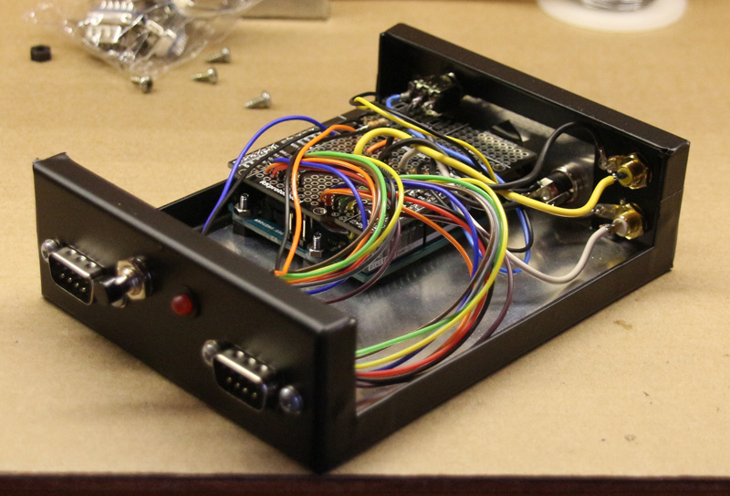
Sticky-backed plastic (Fablon) gives a good exterior finish, and is far-less hassle than painting:
Internal construction
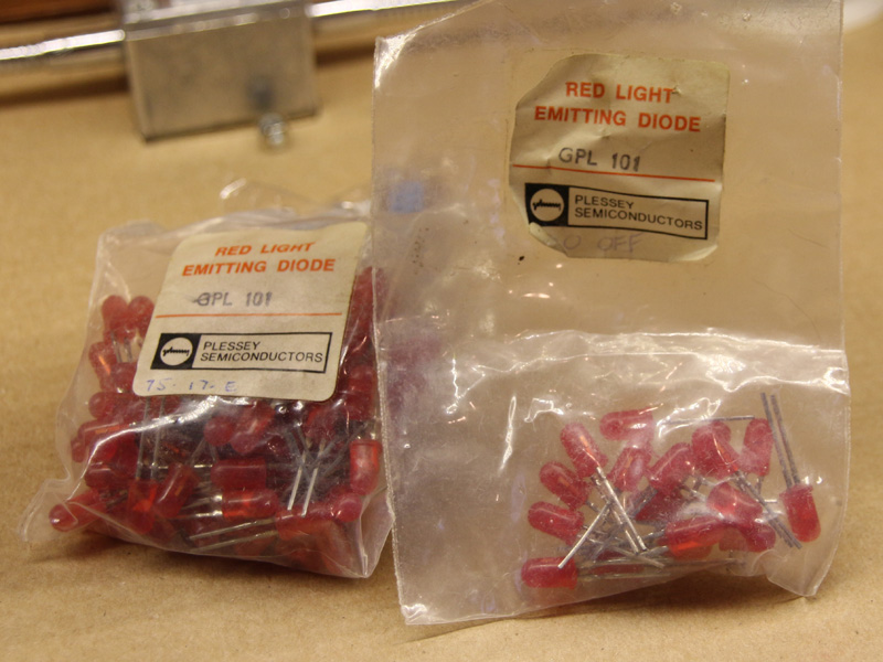
My grandfather used to work for Plessey back in the 70s – these LEDs found their way into his workshop…
Ancient LEDs
Woodgrain Fablon for the authentic ‘retro’ look:
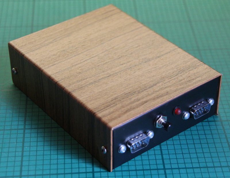
Finished console – Front
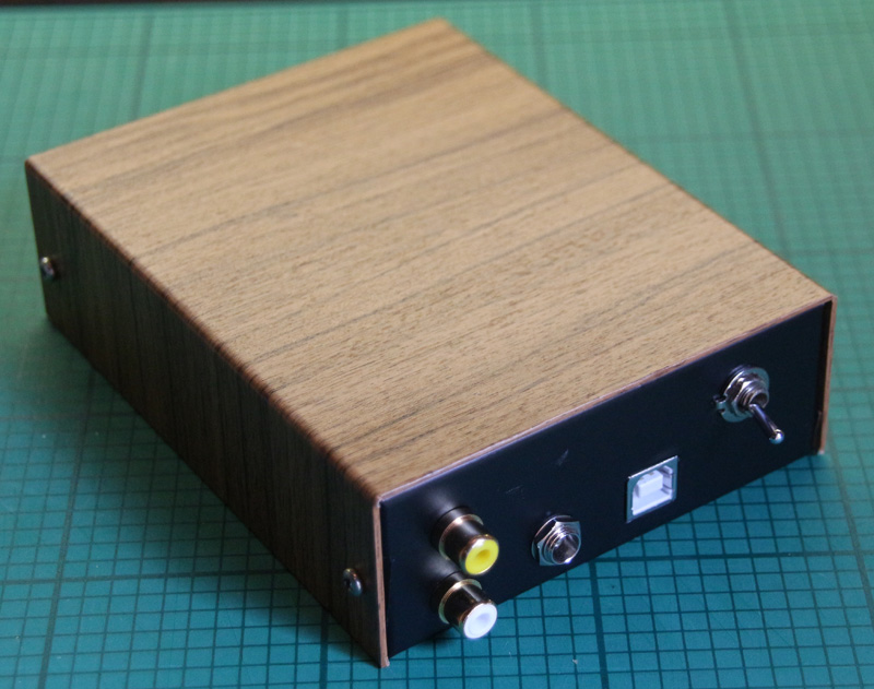
Finished console – Rear
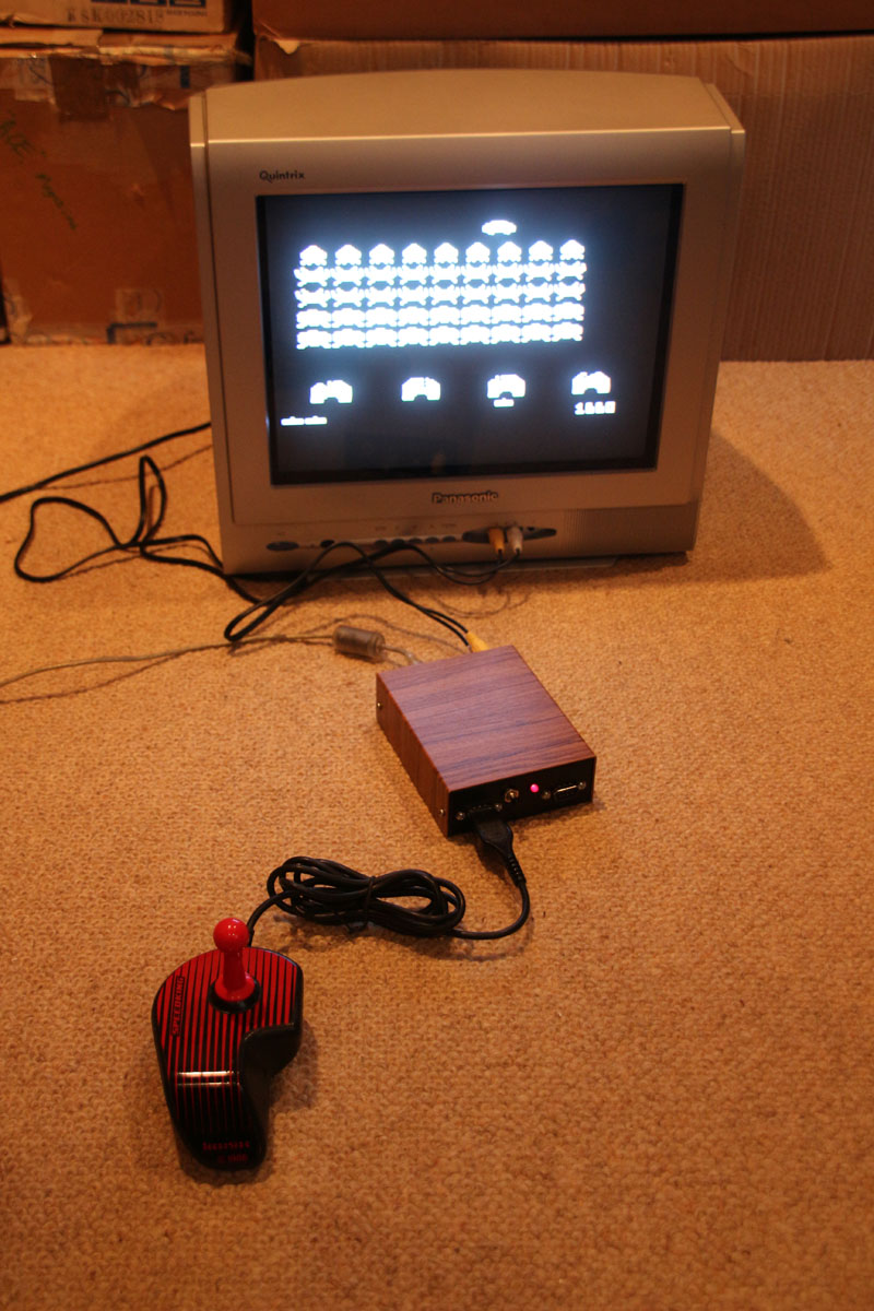
Hackvision Space Invaders
I intend to write a library for the console, however I’ll have to do that at a later date. Since upgrading my Mac to OSX ‘El Capitan’, the Arduino IDE is refusing to upload anything to any of my Arduinos. I’ll get around to it when I get it fixed.
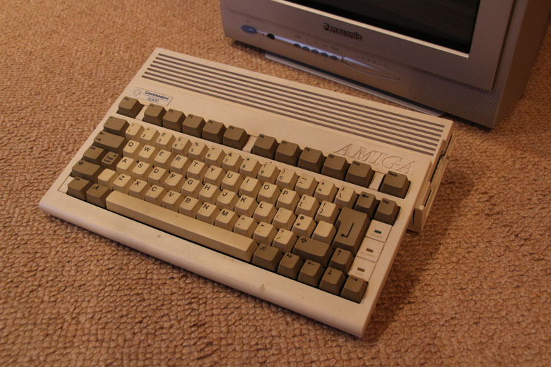
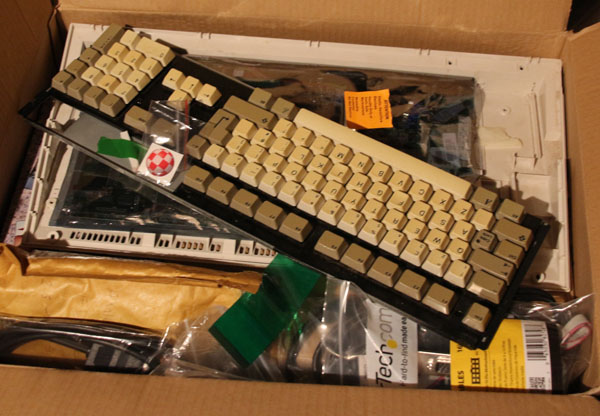
My Amiga 600 was a car-boot sale find about 10 years ago. In an time when the Playstation 2 was past its peak I managed to buy it for £5. It came with loads of disks, PSU and a couple of joysticks.
Amiga 600
After testing it to confirm it worked I’m ashamed to say that it simply got put back in a box and consigned to my loft for the next decade…
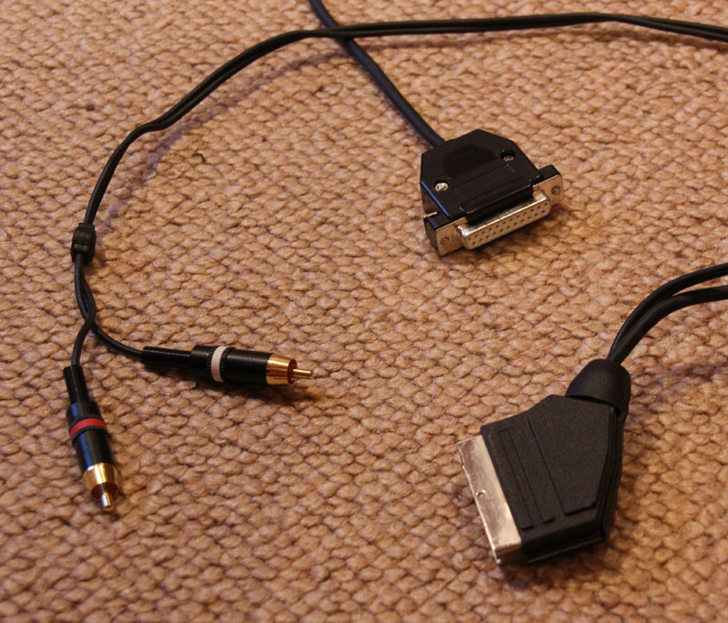
Well, as part of my on-going project to ensure that my old tech is more usable I decided to resurrect it. First things first – did it still work? Fortunately, I not only have an old-but-good Panasonic Quintrix CRT TV, but I also hung onto my Amiga to SCART cable. This is not as trivial as it sounds. Many older games consoles and computers used standard connectors for their various interfaces that are still common today, but the Amiga’s monitor port used a 23 pin ‘D’ connector. These are all-but impossible to find nowadays. It’s possible to buy Amiga monitor cables, but most of them use the common 25 pin ‘D’ with two of the outer pins cut off – it works, but it’s hardly elegant.
Amiga RGB SCART cable with very hard to come by genuine 23 pin ‘D’ connector
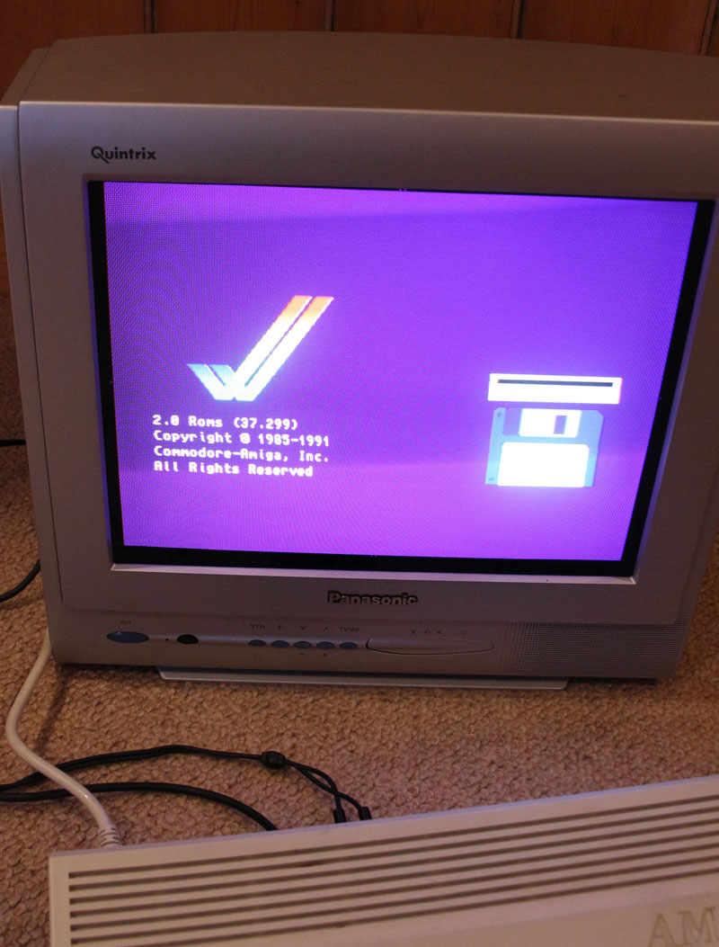
I plugged everything in, flipped the power switch, and was greeted with the boot screen.
A600 boot screen – it still works
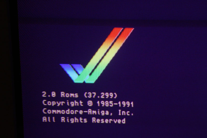
The good news was that it still worked, the bad news was that it only had the 37.299 ROM installed rather than the final 37.350 required for booting from a hard drive above 40MB.
37.299 ROM
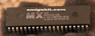
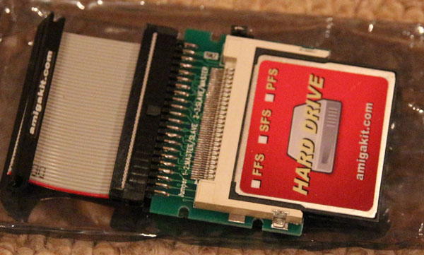
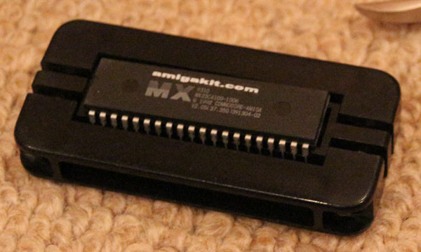
The Amiga still has quite an active community of enthusiasts, so getting hold of a new 37.350 ROM wasn’t a problem. It is also no longer necessary to use an actual hard disk drive, as its possible to use a relatively simple and inexpensive Compact Flash card adapter instead. I purchased the ROM, CF adapter and CF card from amigkit.com. The CF card came pre-loaded with auto-booting software to install the Workbench, etc. on the card.
Kickstart 37.350Compact Flash to 44 pin IDE adapter
Time to breakout the toolbox to get at the motherboard.
A600 motherboard
Replacing the Kickstart ROM is fairly straightforward, but there are a couple of gotchas. If you’re not used to dealing with ICs then know that they usually come with their pins splayed-out a bit, but to use them the pins have to point straight down. There are two mains ways of doing this – using a pin straightening tool, or carefully bending the pins against a flat surface (usually a desk) one row at a time. If you’re going to be doing this procedure a lot, then do yourself a favour and get the proper tool. They’re not expensive, get the job done reliably, and are far quicker to use.
Pin straightening tool
The next gotcha results from a rather bizarre decision made by the designers of the A600 motherboard – while the Kickstart IC has (a very standard) 40 pins, the IC socket on the motherboard has 42 pins (I didn’t even know 42 pin sockets existed!). If, like me, you plug the IC into the socket incorrectly then not only will the Amiga not boot up, but the new Kickstart IC will start to get very hot indeed! I realised what had happened before the IC caused itself or the Amiga irreparable damage. The photo shows the correct orientation and alignment the IC on the motherboard of my A600 – board layouts and specs can change between revisions, however, so if you’re going to do this yourself then the best way of determining the correct way of inserting the new IC is to take careful note of how the original one is oriented/aligned.
New Kickstart ROM inserted into socket
Installing the new Kickstart IC (correctly!) yields the following on the boot screen:
37.350 ROM
Time to install the CF adapter, which is connected where the hard-drive would’ve been connected. Make sure you push hard enough to make a proper connection – when being extra careful with vintage hardware it’s easy to convince yourself (as I did) that the connector is seated properly (when it needs a bit more of a shove!).
CF card acting as HDD
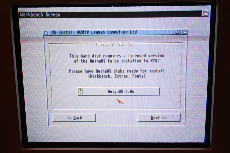
Booting up takes you straight into the Workbench install utility that was pre-installed on the CF card – have your system disks ready and just follow the instructions.
Installing Workbench on “HDD” (CF card)
Right, that’s the A600 up and running properly, now whatever happened to my A1200?
In the quest for subjects for blog posts I think this is somewhat “low hanging fruit”.
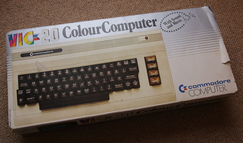
Boxed VIC20
I finally got round to retrieving my old Commodore VIC20 from my parents house. It was a present from my parents on my 14th birthday in July 1982 and changed my life. Still boxed and in pretty good condition, I was pretty confident about it still being in working order – despite having not been powered up for around 30 years.
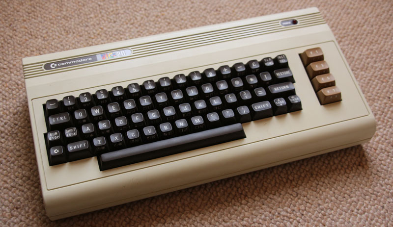
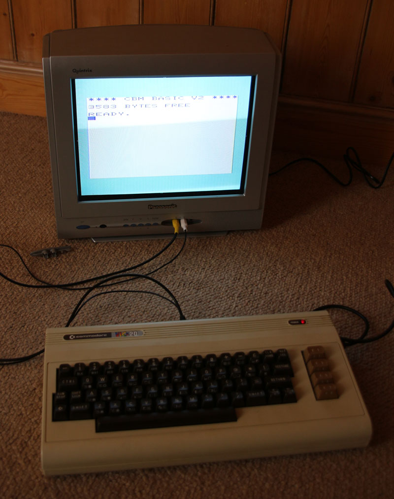
VIC20
After fitting a new plug I connected the power supply and switched it on – the red power LED fired up and no burning-smell/excess-heat was produced! On to try to get a picture from a television…
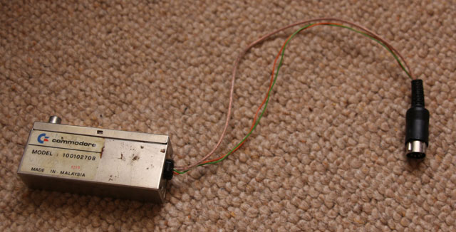
To display a picture on a TV usually involved plugging in the VIC20 to the aerial socket of the TV via the included RF modulator. The picture and sound produced by this horrible thing was pretty atrocious most of the time; the VIC20 does output video and audio directly, but most TVs back in the early 80s didn’t have direct inputs. Things are different now, of course, so it was off to the workshop to make up an AV cable.
Most hated and reviled RF modulator
To make an AV cable for a VIC20 you’ll need:
a 5 pin DIN plug with the pins arranged in a 180 degree pattern
a composite video cable
an audio cable
soldering iron + basic tools
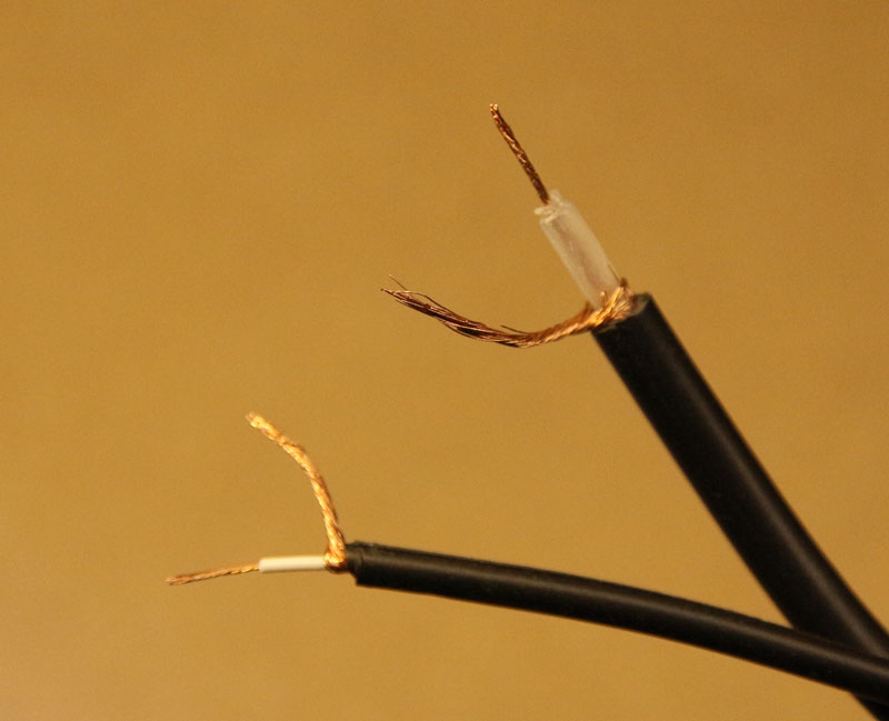
First, make up the video cable so that you have the phono plug on one end and stripped back inner core and shield on the other. Do the same for the audio cable.
Video and audio cablesStripped video and audio cables
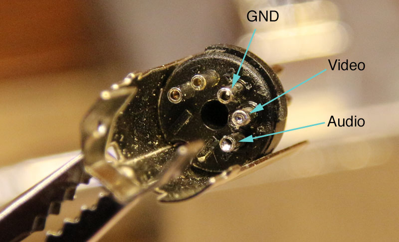
Solder the outer shields of both the video and audio cables to the GND pin, the video to the Video pin, and the audio to the Audio pin (Duh!):
VIC20 AV DIN plug
Re-assemble the plug housing (you did remember to thread the DIN plug boot onto the cables before soldering right?!) and give it a try.
It was supposed to be a simple fix, something trivial to kick the blog off with. Re-soldering one-or-two dry joints and a bit of clean up, I figured.
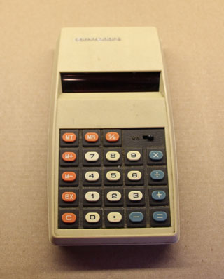
Commodore Calculator (c. Late 1970s)
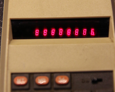
I found my old Commodore calculator in one of the (many) boxes of old tech in my loft. It was given to me as a birthday present by my grandparents in July 1979, and was the first digital device I owned. I was keen to start using it again, but I seemed to recall that it had developed a problem with the display. Sure enough, powering it up revealed that the upper-right segment of the least significant digit was dead.
That last digit should be an ‘8’
Ok then, out with the screwdriver to see what lies within:
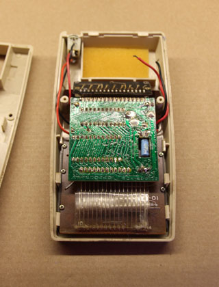
Simple circuit board, coarse soldering, cat hair.
Yes, during initial inspection I discovered several fine hairs that almost certainly originated from my long departed cat, Tom. Quite how they managed to work their way in I have no idea (one was actually under the display lens cover!)
Tom – despite appearances to the contrary – one of the smartest cats who ever lived.
Folding back the main (err, only) board to revealed the display, and the realisation that this wasn’t going to be the easy fixed I’d hoped, if possible at all.
Yes – back in the 70s even simple calculators had DC input jacks!
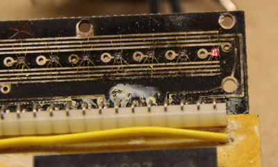
It occurred to me that it wasn’t going to be a simple dry-joint re-soldering job. The individual digits in the display were multiplexed, so a simple bad connection between the display and the main board would’ve manifested itself as something like either a whole digit or the same segment in all digits being dead.
Display lens cover (just how did a cat hair work its way underneath?)
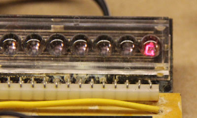
Prizing off the lens cover caused my heart to sink – the digits were absolutely tiny, and were connected to the PCB by wires finer than a human (and cat) hair:
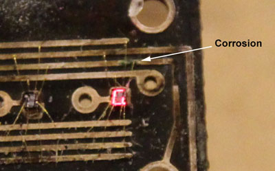
I quickly located the source of the problem – the track in the place where the dead segment was connected was very corroded:
Corrosion – in the worst place.
Well, using a soldering iron was totally out of the question, so I called it a day and hoped a solution would present itself. I have a rule when it comes to faulty old tech, I call it the rule of Three ‘R’s: Repair, Repurpose, or Rubbish. I’d hate to have to junk the thing for such a simple defect. There had to be a way.
The answer came to me using technique I’ve honed over many years of mental training – I give in and go and do the washing-up/re-arrange the fridge/vacuum the lounge/etc.
Electrically conductive silver paint instead of solder turned out to be the answer, there’d be no heat and I could apply it with a fine point. If you’re in the UK then Maplin sell it (http://www.maplin.co.uk/p/electrically-conductive-silver-paint-n36ba) – its the same stuff that you use to repair broken tracks in heated rear car windows.
To be honest, applying it with a cocktail stick while wearing a pair of glasses plus double jeweller’s loupes wasn’t ideal and resulted in a blob across several tracks. Once it had dried I managed to scrape away the parts of the paint that would’ve caused unwanted shorts, and by some miracle it actually worked. I think it was just as much luck as judgement, but, hey, it all counts!