This project was a real “Parts-bin Special”; made up from a load of stuff I’ve had hanging around at the bottom of boxes for years. What it does is pretty useful to me, though.
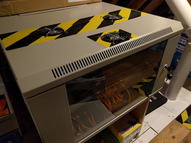
Last year I networked my entire house with a gigabit LAN. CAT6A cable runs from RJ45 sockets all over the house up to the loft where they are terminated at a patch-panel in a 6U 19 inch rack-mount cabinet. This cabinet houses a 24-port switch, router, cable-modem, and a server (an Intel i5 with 8GB of RAM in a 2U case, in case you’re interested). For a few days last year the sun did actually shine on my house, and subsequently the temperature in the loft rose alarmingly quickly. The power led on the cable-modem changed from blue to pink – a quick visit to Google confirmed that it was getting too hot. My quick fix consisted of running a couple of old CPU fans over the modem and router, and removing the door and side-panels of the cabinet. It worked, but was hardly a long-term solution.
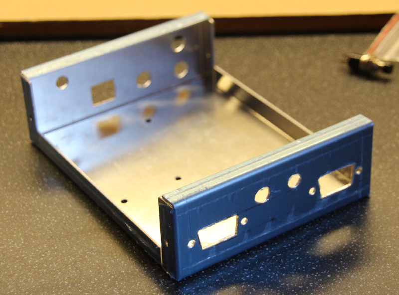
There was nothing for it but to break-out the power-tools, and cut holes in the cabinet to permanently fit some fans.
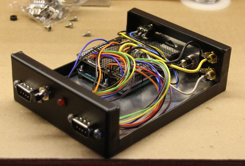
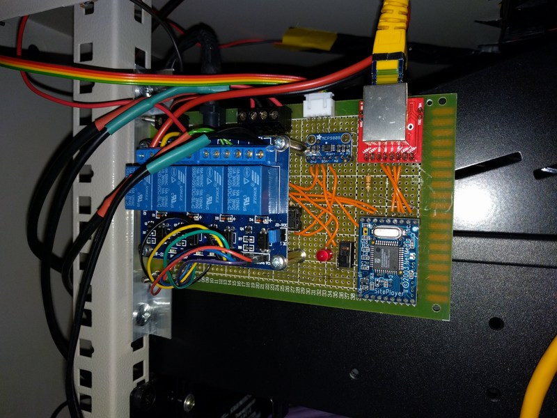
All well-and-good, but how to control the fans? I was glad to finally find a use for the following stuff that I’d probably bought for various long-forgotten projects!:
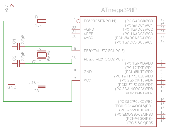
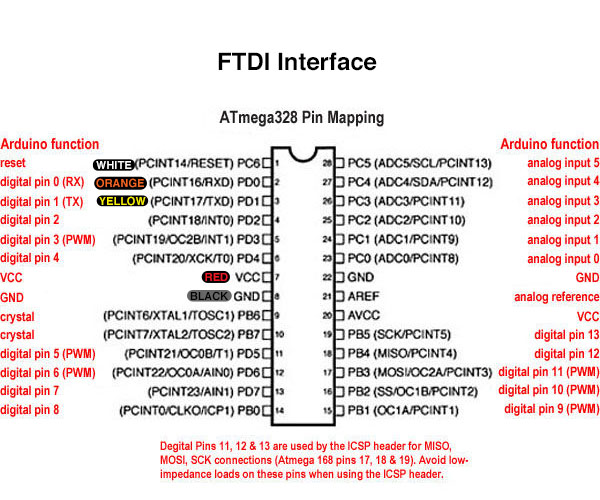
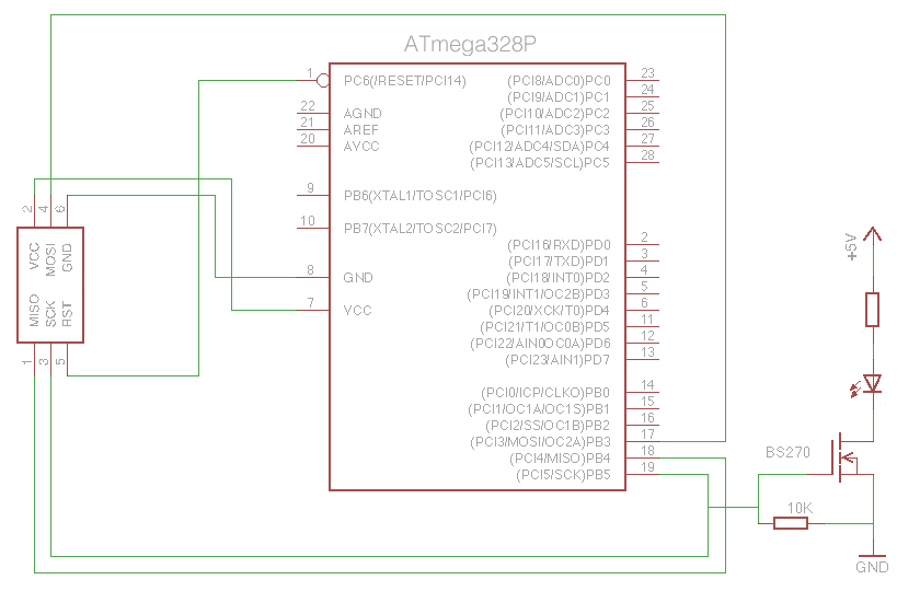
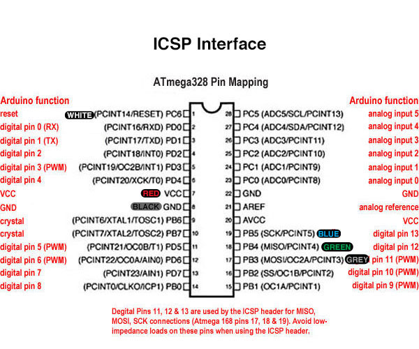
- ATMega328P Microcontroller
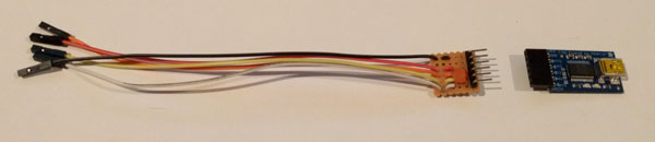
- SitePlayer Embedded Webserver
- 4 Channel Relay Board
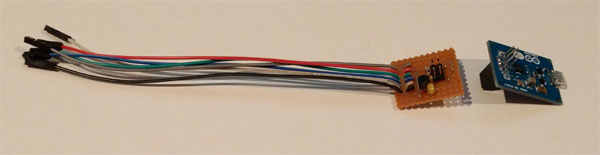
- MCP9808 Temperature Sensor Breakout Board
- HTU21D-F Temperature/Humidity Sensor Breakout Board
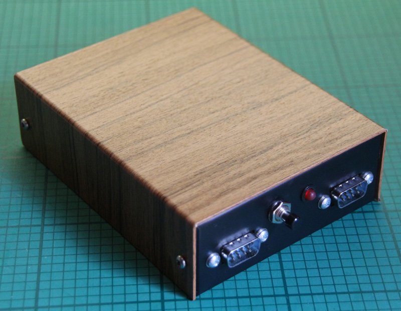
When built, programmed, and mounted in the cabinet it give me the following functionality:
Fan Control
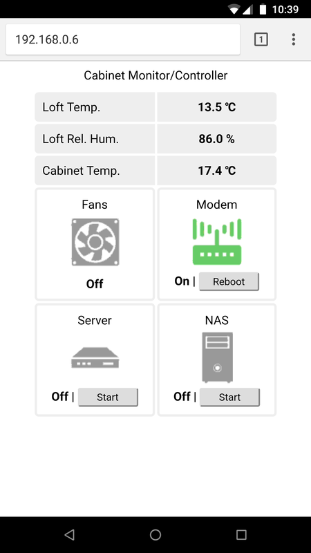
When the cabinet temperature (measured by the MCP9808) reaches 30°C the fans switch on. They will only switch off when the cabinet temperature falls below 26°C. If the server is running then the fans are switched on regardless of the cabinet temperature.
Cable Modem Control
Very occasionally the cable-modem needs rebooting. Being mounted in the loft used to mean that someone (that would be me, then) would have to climb up the ladder to pull the power from the back of the modem, wait 30 seconds, then reconnect it. Somewhat inconvenient. The modem power is now routed through one of the relays via its normally-closed connection which can be switched remotely.
Server & NAS Control
The server and NAS have their power switches connected in parallel with 2 of the relays, allowing a simulated button-push to turn them on and off.
Loft Temperature & Humidity Monitoring
The HTU21D-F is mounted outside the cabinet to provide monitoring functions (no reason for this, really – it was just easy to add!)
All the above is accessed via a mobile optimised web-page:
The take-away from this post is this:
You probably can build something cool from the long-forgotten components you already have – get to it!