After using pre-built Arduinos the next step is to ‘roll your own’. It may not have the niceties of built in USB/debug-console, but it’s fully functional (and much cheaper!).
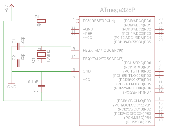
There are plenty of tutorials on DIY Arduino compatible circuits, so there’s no point duplicating that information here. As a reminder, however, here is what you need to make a minimal Arduino:
- AVR ATmega328 Microcontroller
- 16MHz Crystal
- 22pF Capacitor (x2)
- 10k Resistor
- 10uF Capacitor
So far, so good – but with no built-in USB interface you’ll have to use either an FTDI interface (for ATmegas with a bootloader already installed), or an ICSP interface (for blank ATmegas).
FTDI Method:
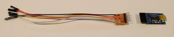
To use this method you’ll need an ATmega328P that has had the Arduino bootloader pre-installed. This is a small piece of code that allows sketches to be uploaded via the microcontroller’s serial link. You’ll also need a USB to FTDI interface. I wholeheartedly recommend Adafruit’s FTDI Friend product.
The FTDI interface is connected to the ATmega328P thus:

Building in a programming header into your project that plugs directly into the FTDI interface can be a bit of a pain – routing the connections around the circuit takes time and space, and adds to the complexity. I prefer to simply put header pins next to the relevant ATmega pins, then use an adapter with flying leads. Another advantage is that the 0.1uF capacitor can be built into the adapter, as its only required when programming the device.
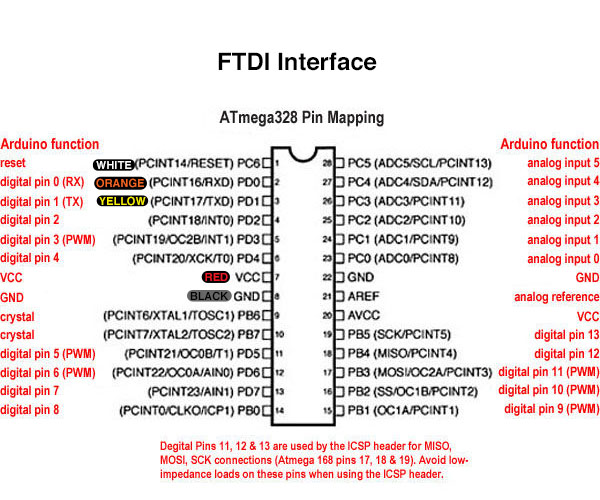
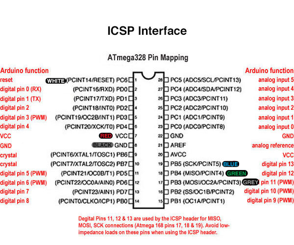
Another good idea is to make a handy reference to remind you what goes where. Print this out (laminate it if you can) and keep it with the adapter:
ICSP Method:
For this method you’ll need an ICSP interface. You’ve got a lot of options when choosing one. I use the official ArduinoISP – although it is apparently no longer made.
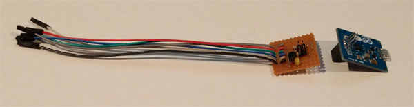
One of the things I don’t like about the ArduinoISP is the lack of status LEDs showing activity. Adafruit’s FTDI Friend features blinking LEDs whenever data is transmitted or received, which is a great sanity check when things don’t quite work out the way you expect. I built an ICSP programming cable that flashes an LED every time the SCK pin goes high (as you can imaging, this pin is very active during programming). The LED is driven via a BS270 MOSFET as connecting an LED/resistor directly would interfere with the data transfer (why a BS270? – it’s what I had lying around in my parts collection!). As a bonus, programming the ATmega with the test ‘Blink’ sketch will flash the LED, as the ATmega’s SCK pin maps to the Arduino pin 13.
Here are the connections for ICSP programming:
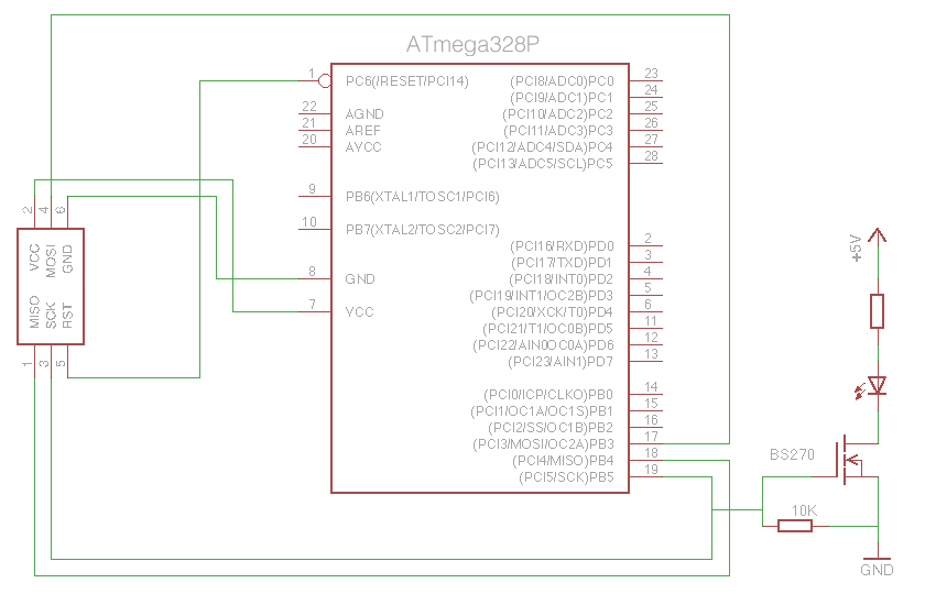
Using a 3mm LED with built-in resistor saves space:
Once again, make a handy reference card, and keep it, err, handy:
** ICSP GOTCHA **
Here’s a tip that may save you a few headaches. If after programming a completely blank ATmega for the first time the sketch seems to run really slowly, then try burning the bootloader first, then reload your sketch afterwards. The bootloader will be erased, but when burning it the Arduino IDE also sets certain settings in the ATmega correctly for Arduino compatible operation (specifically, it sets the device to use the external 16MHz crystal oscillator rather than the 1MHZ internal one).

