In part 1 we implemented a simple electronic dice using an Arduino (R3). Part 2 implements the same (slightly enhanced) dice using a PIC 12F629 microcontroller.
So, why use a stand-alone microcontroller rather than an Arduino? Several reasons; the PIC 12F629 is a lot cheaper than an Arduino (its even cheaper than the AVR chip that the Arduino is based upon), it’s 8-pin DIL package makes it a lot smaller than an Arduino, and finally, it uses a lot less power than an Arduino.
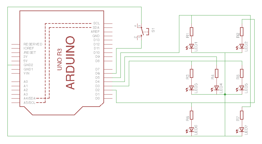
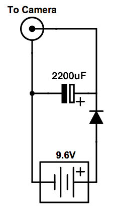
Here’s the schematic for the new dice circuit:
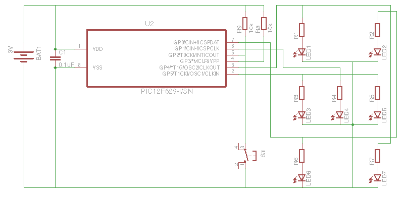
The LEDs and their matching resistors are connected to GPIO pins configured as outputs in much the same way as before. One thing to watch out for is that while the Arduino can sink/source up to 40mA per pin, the PIC can only manage 25mA. This isn’t a problem here as 25mA is more than enough to drive pairs of the 3mm LEDs with their built in resistors.
The push-button switch is connected between ground and a GPIO pin configured as an input that is being pulled high with an external 10k resistor. Yes, PICs do have built in pull-ups, but I’ve not used them here (read on to see why!).
The reset pin is also being pulled high with an external 10k resistor. This pin can be configured as an GPIO with the reset being held high with an internal 10k resistor, but there’s a weird issue regarding the 12F629 that means it’s best to use an external pull-up on reset if you’re; a) planning to also use the internal oscillator, and b) programming the PIC with a PICkit 3 programmer.
The 0.1uF capacitor across the supply pins is to filter out any noise in the power supply (probably unnecessary in this case as I’m powering the whole thing from a battery).
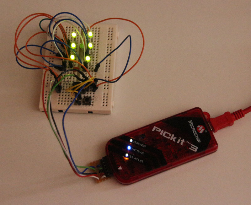
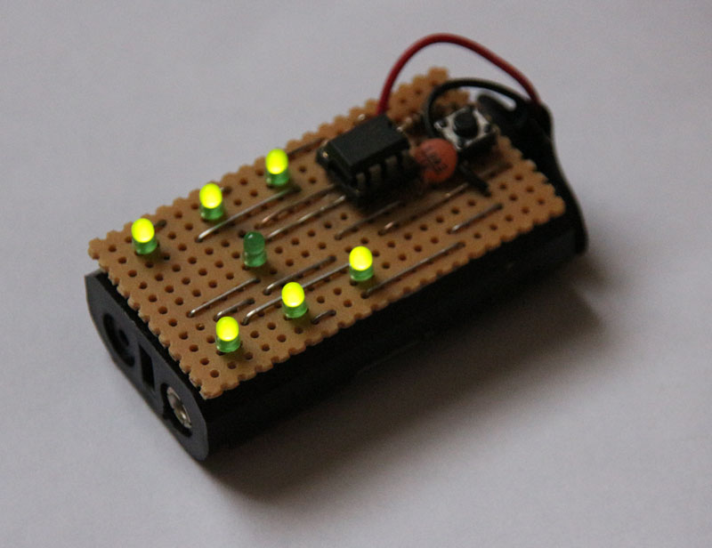
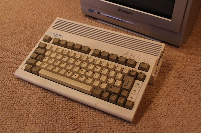
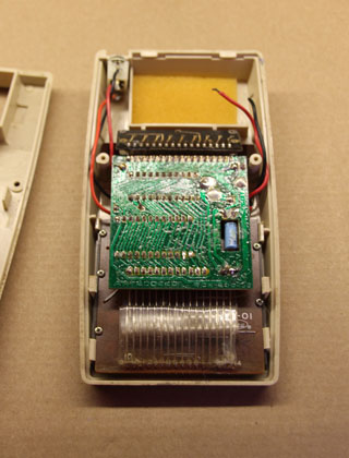
PIC12F629 dice circuit on prototyping board
Explaining how to code in assembler is well beyond the scope of this post, but if you’re in the process of learning then the code is commented so may be of some help:
;**********************************************************************
; Electronic Dice
;**********************************************************************
; Filename: dice.asm
; Date: 11-Aug-2015
; Author: Simon Buckwell
;**********************************************************************
; Files Required: P12F629.INC
;**********************************************************************

 list p=12f629 ; list directive to define processor
 #include <p12F629.inc> ; processor specific variable definitions

 errorlevel -302 ; suppress message 302 from list file

 __CONFIG _FOSC_INTRCIO & _WDTE_OFF & _PWRTE_ON & _MCLRE_ON & _BOREN_OFF & _CPD_OFF & _CP_OFF

; '__CONFIG' directive is used to embed configuration word within .asm file.
; The lables following the directive are located in the respective .inc file.
; See data sheet for additional information on configuration word settings.

;***** PORT
; output
led_1and7       equ 0x04
led_2and6       equ 0x00
led_3and5       equ 0x05
led_4           equ 0x01
button          equ 0x02

; counters
d0              equ 0x20
d1              equ 0x21
d2              equ 0x22

;**********************************************************************
         org 0x000 ; processor reset vector

; initialise device
init
                ; gpio pins all digital
                movlw 0x07
                movwf CMCON

                ; switch to bank 1
                bsf STATUS,RP0
                ; set gpio2 as input
                movlw 0x0C
                movwf TRISIO
                ; enable wake on gpio2 (falling edge)
                bsf INTCON,INTE
                bcf OPTION_REG,INTEDG
                ; switch to bank 0
                bcf STATUS,RP0

re_start
               ; switch LEDs off
                bcf GPIO,led_1and7
                bcf GPIO,led_2and6
                bcf GPIO,led_3and5
                bcf GPIO,led_4

power_down      ; go into power-down mode and wait for wake on INTE
                sleep
                nop

                ; button should be pressed - put back into power-down mode if not
                btfsc GPIO,button
                goto power_down

                ; debounce button (short delay)
                clrf d0
db_loop         decfsz d0,f
                goto db_loop
                ; rotate through dice values
dice_1          ; bit pattern for '1'
                movlw b'00000010'
                btfss GPIO,button
                goto dice_2
                goto display
dice_2          ; bit pattern for '2'
                movlw b'00000001'
                btfss GPIO,button
                goto dice_3
                goto display
dice_3          ; bit pattern for '3'
                movlw b'00000011'
                btfss GPIO,button
                goto dice_4
                goto display
dice_4          ; bit pattern for '4'
                movlw b'00010001'
                btfss GPIO,button
                goto dice_5
                goto display
dice_5          ; bit pattern for '5'
                movlw b'00010011'
                btfss GPIO,button
                goto dice_6
                goto display
dice_6          ; bit pattern for '6'
                movlw b'00110001'
                btfss GPIO,button
                goto dice_1

; display result
display
                iorwf GPIO,f

; 3 second delay
                movlw 0x1a
                movwf d0
                movlw 0x8b
                movwf d1
                movlw 0x07
                movwf d2
delay_loop      decfsz d0,f
                goto delay_hop0
                decfsz d1,f
delay_hop0      goto delay_hop1
                decfsz d2,f
delay_hop1      goto delay_loop

; return to re_start
                goto re_start

; end
end
The design makes use of the low-power feature of the 12F629 which allows it to be permanently connected to a battery without draining it quickly. I tried measuring the current draw while in its powered-down state, but my digital meter simply doesn’t go that low (we’re talking nano-amps!).
(If you’re a PICMicro novice then be assured that low-power mode and interrupts are quite advanced topics, so don’t worry if the following doesn’t make sense)
I’d never used low-power mode before so I fell for a couple of ‘gotchas’:
Firstly, I simply couldn’t understand why the device was drawing so much current in power-down mode. Even with all the LEDs turned off, and only using external pull-ups (as per the docs) it was still drawing too much current – not a vast amount, but enough the drain the batteries in about 6 weeks. Upon reading the docs in more detail I read that the brown-out detect circuit uses a fair amount of current – once that was disabled the current draw fell to an amount I could’t even measure.
Secondly, sometimes after displaying the required random number pattern it would immediately display the pattern for a ‘1’ without the button being pressed. I immediately though that it was a switch debouncing issue, and I was right, but not in the way I initially thought. While I’d set up the button detection correctly – enabling interrupts on a falling edge of INT (pin 5) while disabling global interrupts – I hadn’t realised that the falling edge was being detected while not in power-down mode, and was ‘remembered’ when power-down was entered causing an immediate re-triggering. A simple test after the sleep instruction rejected these false triggerings.