In the desparation to write something, anything, every month for the blog it’s easy to forget that the post really needs to contain at least one piece of useful information. This month, then, I shall provide the answer to the question “Can I run a longer cable from my Virgin Media wall-box to my Superhub (Modem/Router)?”.
TL;DR answer: Yes.
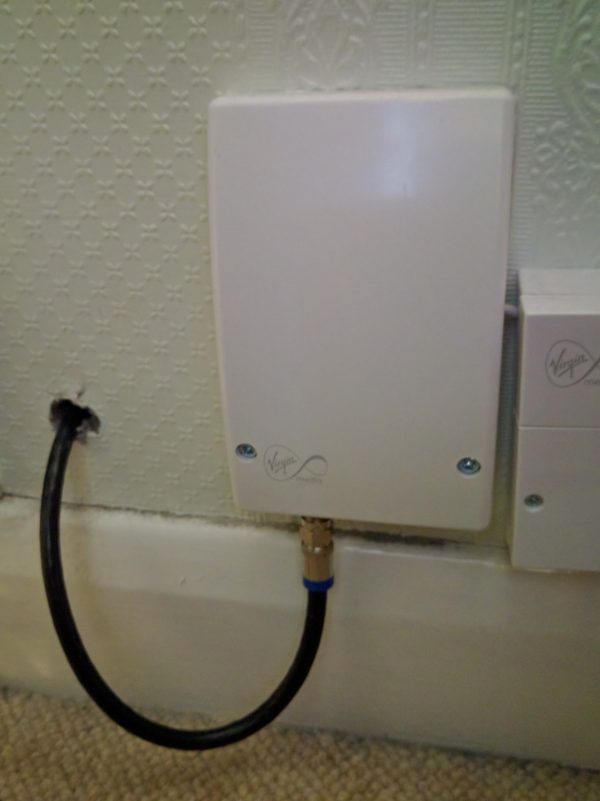
I wanted to have the central point of my home network in the loft of the new house, but the wall-box installed by the Virgin Media engineer was put into the corner of the living room. It was installed one the day we moved in, and in all the chaos it was just easier to have it put in the place the engineer found easiest (even if it was the worst possible position). I asked him if there was a limit on how long the cable can be from the box to the SuperHub. His response: “Nah, not really”. I thought I’d give it a go myself.
Virgin Media wall outlet
Virgin Media used RG6 (75ohm) cable, but I bought a 100m drum of Webro WF100 (slightly better, but still 75ohm) – way more than I needed for the job, but I can use it for TV signal distribution (when I get round to it).
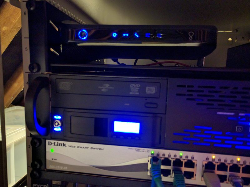
Threading cable through any building can be a filthy awkward job, and this was no exception. Once in place, however, terminating the cable with compression-fit F-connectors was simple enough. After connecting up at both ends and applying power the SuperHub eventually locked-on to its signal. A quick look at the SuperHub’s admin interface confirmed that it was truly working.
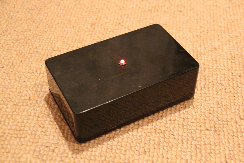
Superhub 2ac (running in modem mode) mounted in rack
So, “Yes”, it is possible to replace the 1m provided with a 15-20m cable.
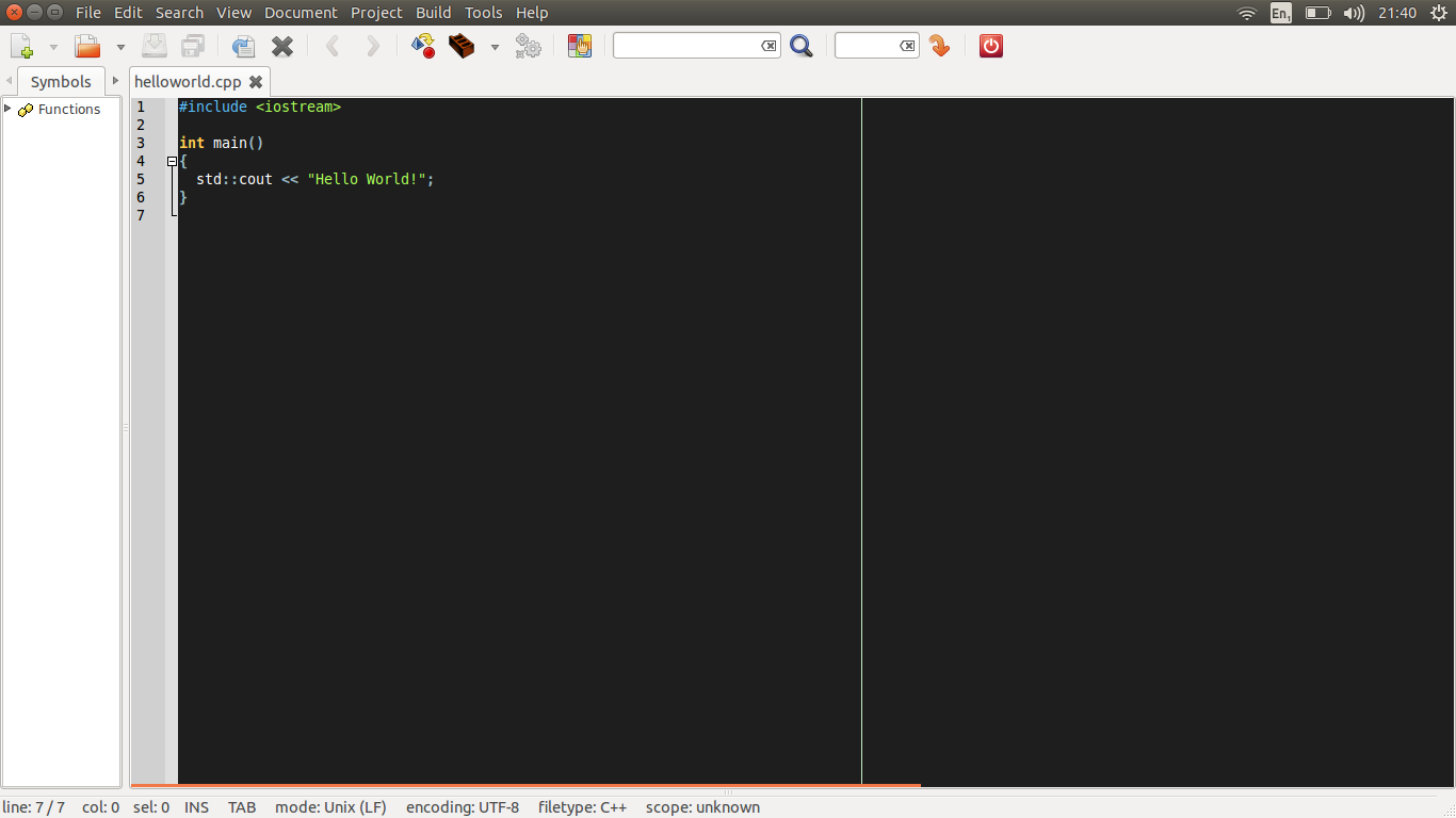
When you fire-up your modern IDE, chances are that there is a vertical line running down the text editing area:
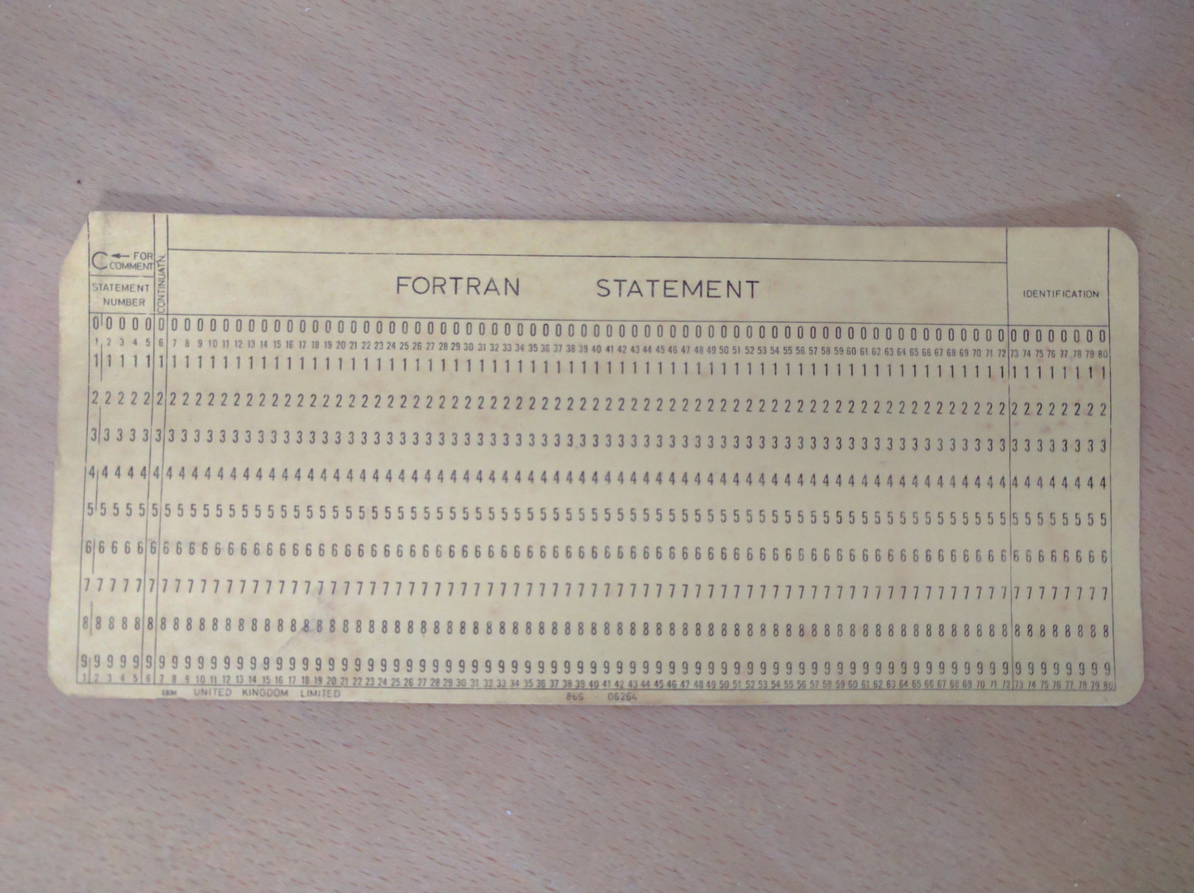
Do you know why this line it there? Well, this line marks the 80th column of text, which many coding standards define as the longest that a single line of code should be before wrapping onto the next line. Give yourself +1 points if you thinks that’s why the 80th columns marker is displayed.
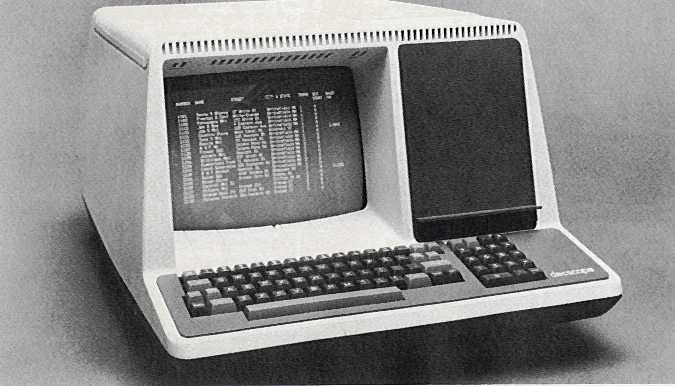
OK, but why 80 columns in particular? If you then say “But Simon, that’s because old computer terminals could only display 80 columns”, then give yourself another +1 points:
The IBM punched card was used in the 1950s and 1960s by IBM and others to store data and code for processing by computer. The 80 column punched card predates even this, however – IBM designed the format in 1928 for storing numerical data for processing using semi-automatic electromechanical data processing equipment.
So, your modern IDE has a feature that relates to design decision made in the 1920s.
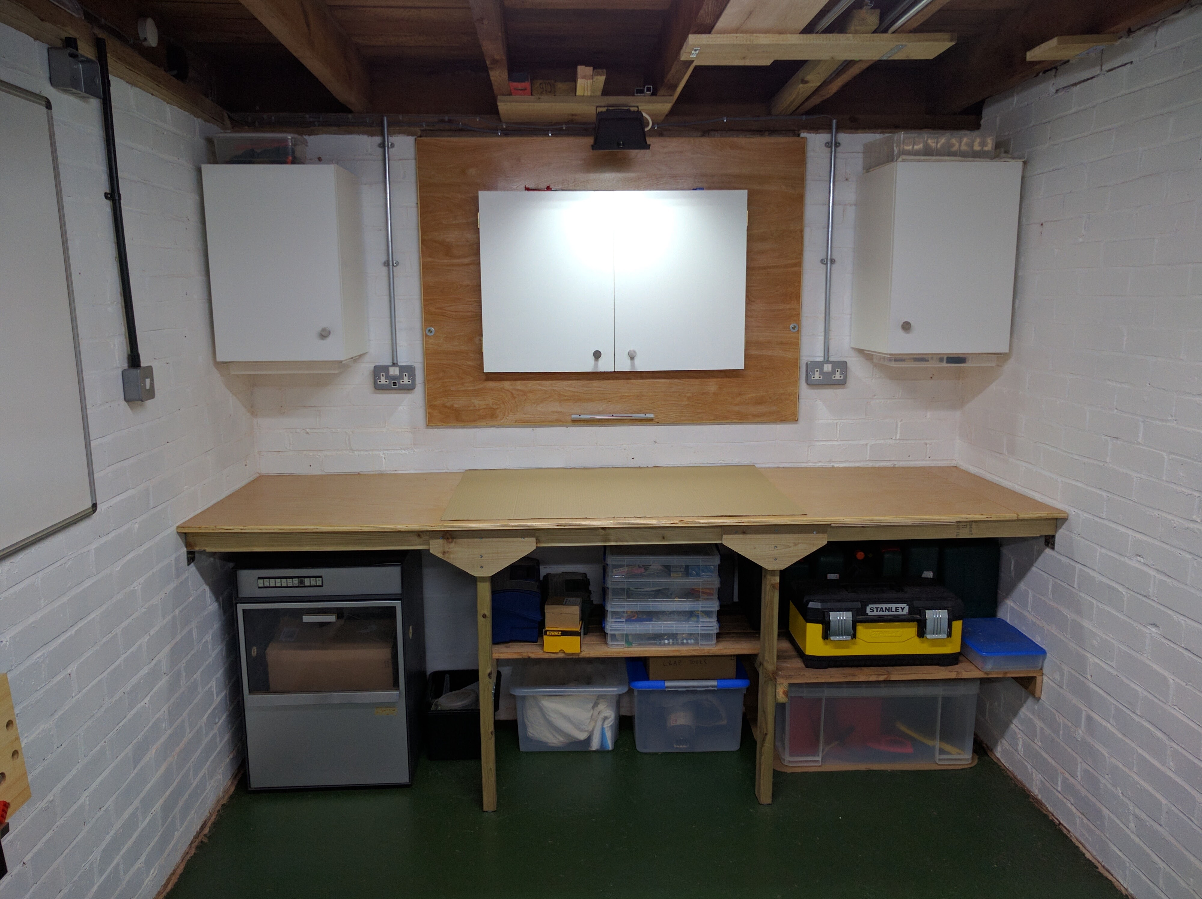
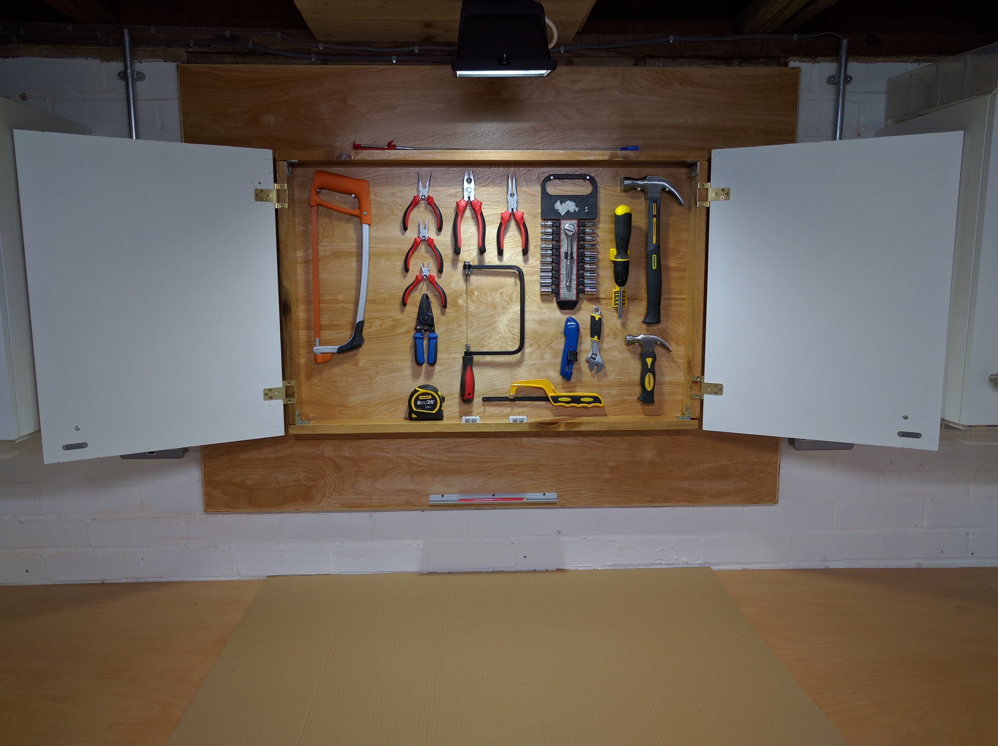
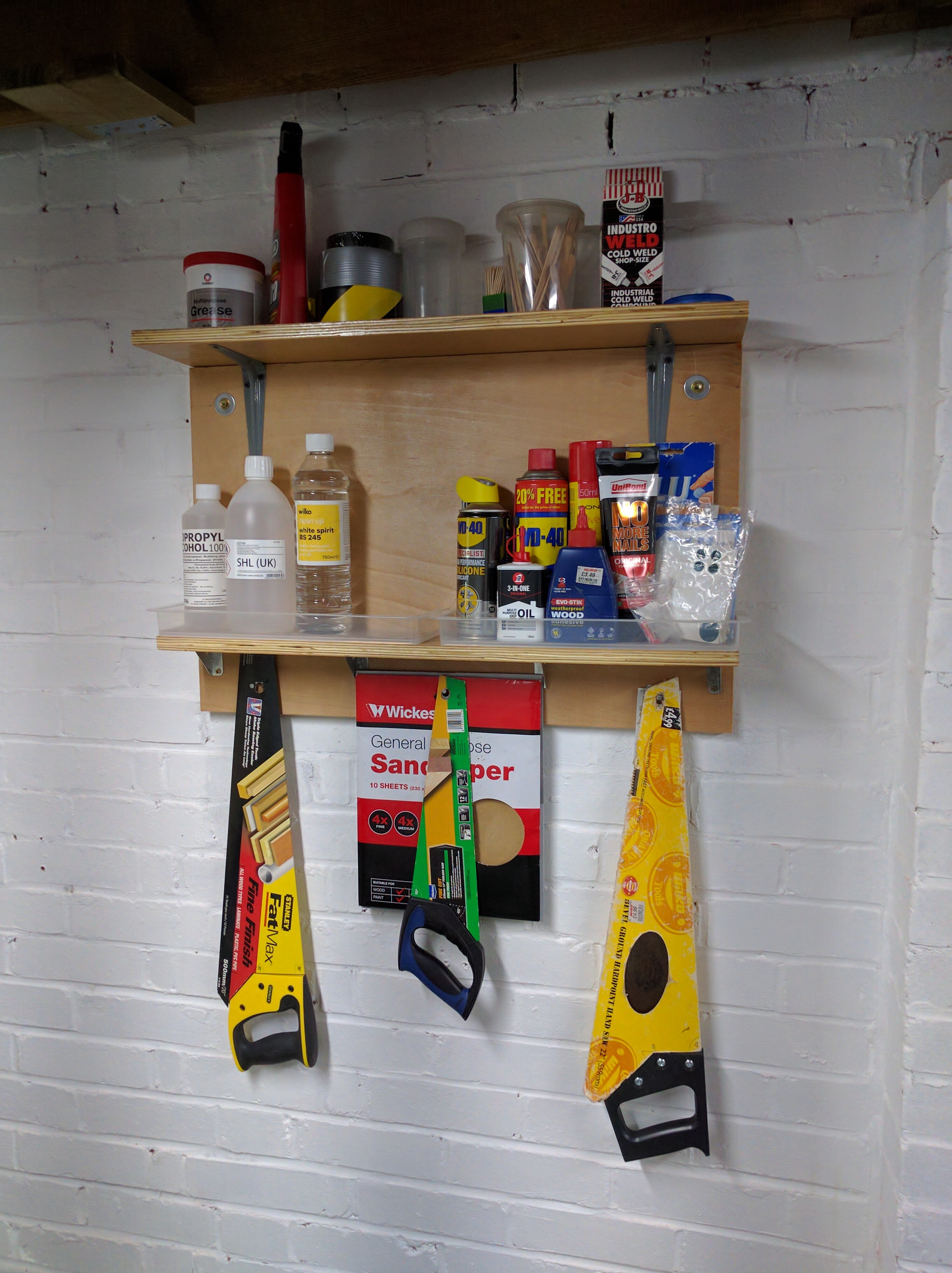
The maker-space is finally complete. Well, “complete” in the sense that it’s 99% complete. There are always minor jobs and additions to do, as is always the case with work-spaces; they keep evolving.
Most important development tool!Place for all the nasty gooey stuff
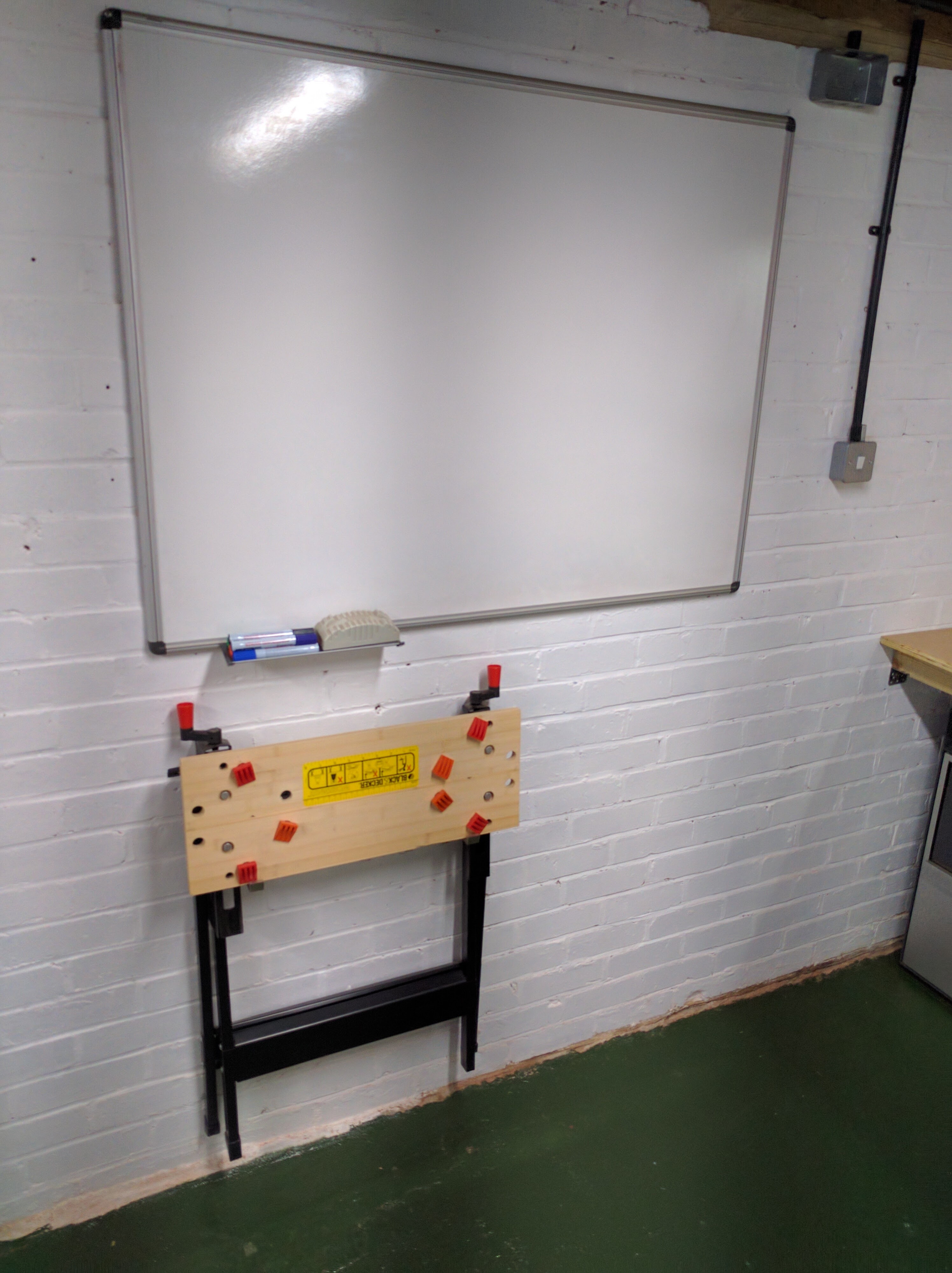
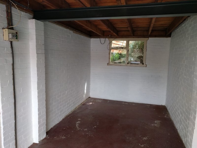
Finally got started on the workshop. I removed the wood and nails that provided the makeshift storage among the beams, then removed the faulty fluorescent light before treating all the remaining woodwork with a universal wood treatment solution. The walls were then painted with white masonry paint, and the metal beams with green metal paint.
Cleared and painted
I’m waiting for the floor paint to be delivered, and once that’s done I can think about getting the electrics installed, and fitting a bench and storage.
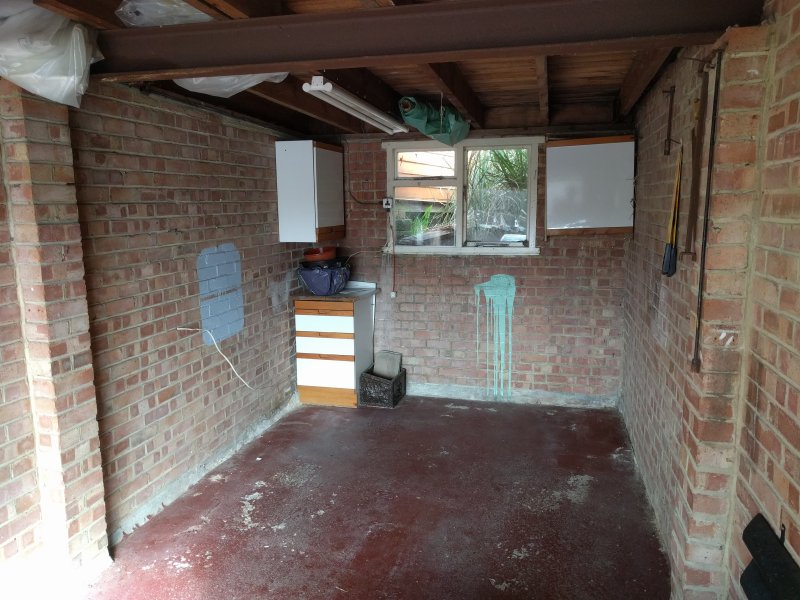
It was a long time coming, but I have finally moved house! After the chaos, stress and confusion of moving my prediction that I would have a functioning maker-space set up “very quickly” was hopelessly optimistic!
Before the transformation
I’m making the setting up of this space a priority. It kind of makes sense to; a functioning workshop will be useful when working of the rest of the house.
It was intention that my February 2016 post would be the start of the chronicling of the construction of the maker-space in my new house, but that turned out to be wishful thinking, as we haven’t moved in yet. Maybe next month…
Anyway, as I’ve no projects to show due to my current workshop having been packed up into crates, I though that I’d share this piece of video that I found languishing on an old VHS tape in my loft. It’s an excerpt on the latest developments in virtual reality from the BBC science & technology show “Tomorrow’s World”, and was broadcast in 1990.
I remember being utterly captivated watching this, and have waited for 26 years for the technology to mature! I really hope that I’m not disappointed when I finally get to try an Oculus Rift, HTC Vive, or Playstation VR…
After using pre-built Arduinos the next step is to ‘roll your own’. It may not have the niceties of built in USB/debug-console, but it’s fully functional (and much cheaper!).
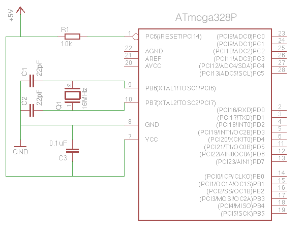
There are plenty of tutorials on DIY Arduino compatible circuits, so there’s no point duplicating that information here. As a reminder, however, here is what you need to make a minimal Arduino:
AVR ATmega328 Microcontroller
16MHz Crystal
22pF Capacitor (x2)
10k Resistor
10uF Capacitor
Minimal Arduino circuit
So far, so good – but with no built-in USB interface you’ll have to use either an FTDI interface (for ATmegas with a bootloader already installed), or an ICSP interface (for blank ATmegas).
FTDI Method:
To use this method you’ll need an ATmega328P that has had the Arduino bootloader pre-installed. This is a small piece of code that allows sketches to be uploaded via the microcontroller’s serial link. You’ll also need a USB to FTDI interface. I wholeheartedly recommend Adafruit’s FTDI Friend product.
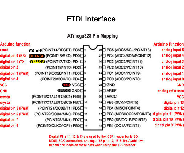
The FTDI interface is connected to the ATmega328P thus:
ATmega328 FTDI Connections
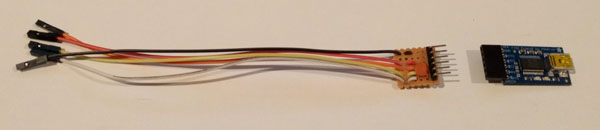
Building in a programming header into your project that plugs directly into the FTDI interface can be a bit of a pain – routing the connections around the circuit takes time and space, and adds to the complexity. I prefer to simply put header pins next to the relevant ATmega pins, then use an adapter with flying leads. Another advantage is that the 0.1uF capacitor can be built into the adapter, as its only required when programming the device.
FTDI Cable
Another good idea is to make a handy reference to remind you what goes where. Print this out (laminate it if you can) and keep it with the adapter:
ATmega328 FTDI Header Pins
ICSP Method:
For this method you’ll need an ICSP interface. You’ve got a lot of options when choosing one. I use the official ArduinoISP – although it is apparently no longer made.
One of the things I don’t like about the ArduinoISP is the lack of status LEDs showing activity. Adafruit’s FTDI Friend features blinking LEDs whenever data is transmitted or received, which is a great sanity check when things don’t quite work out the way you expect. I built an ICSP programming cable that flashes an LED every time the SCK pin goes high (as you can imaging, this pin is very active during programming). The LED is driven via a BS270 MOSFET as connecting an LED/resistor directly would interfere with the data transfer (why a BS270? – it’s what I had lying around in my parts collection!). As a bonus, programming the ATmega with the test ‘Blink’ sketch will flash the LED, as the ATmega’s SCK pin maps to the Arduino pin 13.
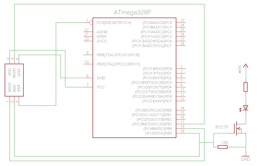
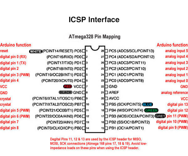
Here are the connections for ICSP programming:
ATmega328 ICSP Connections
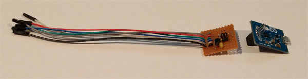
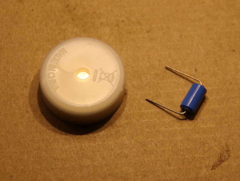
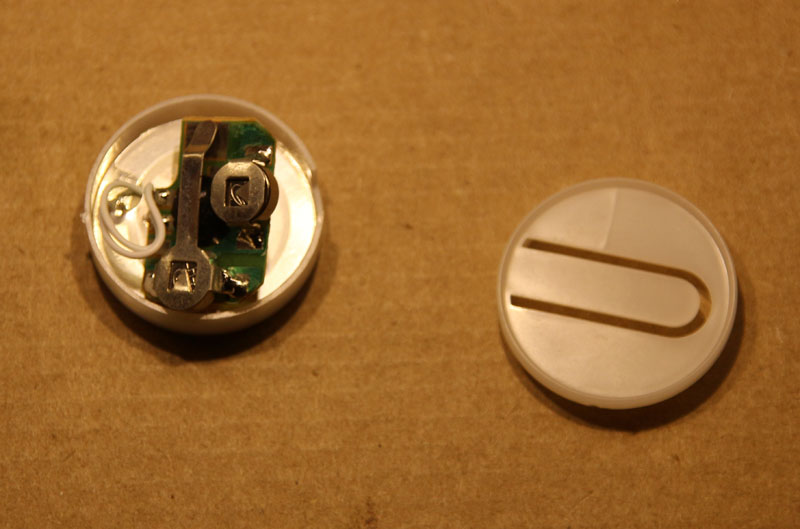
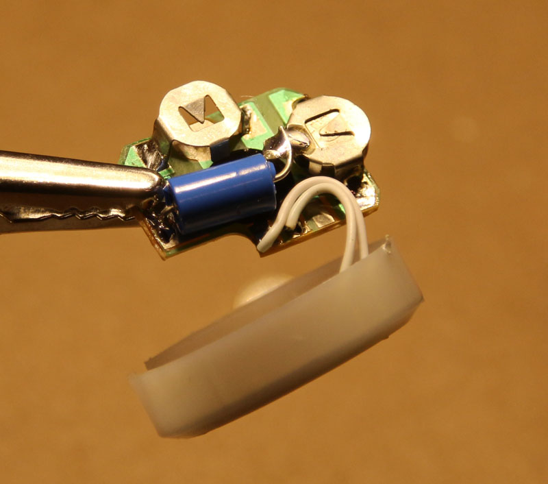
Using a 3mm LED with built-in resistor saves space:
ICSP Cable
Once again, make a handy reference card, and keep it, err, handy:
ATmega328 ICSP Header Pins
** ICSP GOTCHA **
Here’s a tip that may save you a few headaches. If after programming a completely blank ATmega for the first time the sketch seems to run really slowly, then try burning the bootloader first, then reload your sketch afterwards. The bootloader will be erased, but when burning it the Arduino IDE also sets certain settings in the ATmega correctly for Arduino compatible operation (specifically, it sets the device to use the external 16MHz crystal oscillator rather than the 1MHZ internal one).
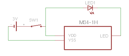
Electronics isn’t just a hobby that can be used for good, y’know. With just a couple of easily obtainable parts, basic tools, and rudimentary soldering skills it’s possible to really annoy people.
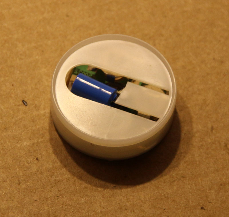
Take those irritating electronic Christmas musical modules, for example. Replace the push-switch with a vibration switch, and it will be activated by the slightest movement.
Parts list:
Electronic music box from greetings-card/novelty
Vibration sensor (really cheap one from eBay or Amazon marketplace)
Music box and cheap vibration sensor
Pry apart the music box exposing the internals – taking note where the switch is located.
Inside music box
Solder the vibration switch in place of the push switch (best to remove the battery before doing this)
Sensor installed
Re-assemble the music box (I had to cut-away part of the push switch to get it back together)
Completed device
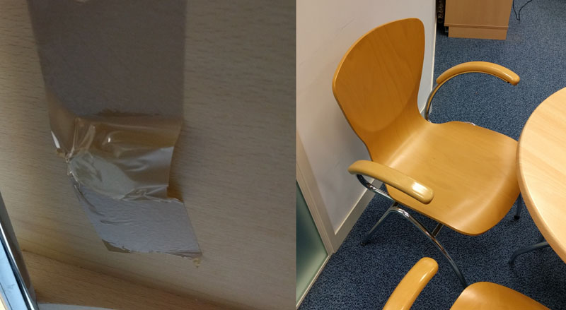
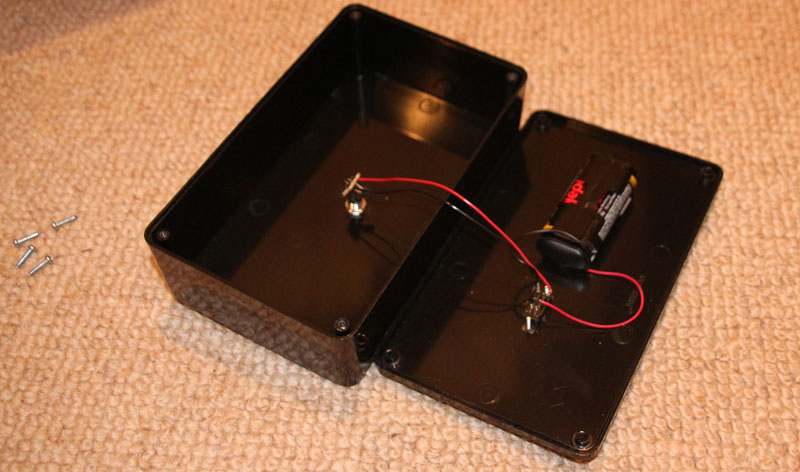
Deploy the device in a place that will be set off by occasional movement. I taped mine to the bottom of a dining chair in the staff kitchen. This turned out to be a bad idea, as it went off so often that once my colleagues had worked out where it was hidden (took them long enough, mind) they took their annoyance out on it.
Discreetly taped to the bottom of a chair
I recovered most of the bits after it had been smash and thrown across the room.
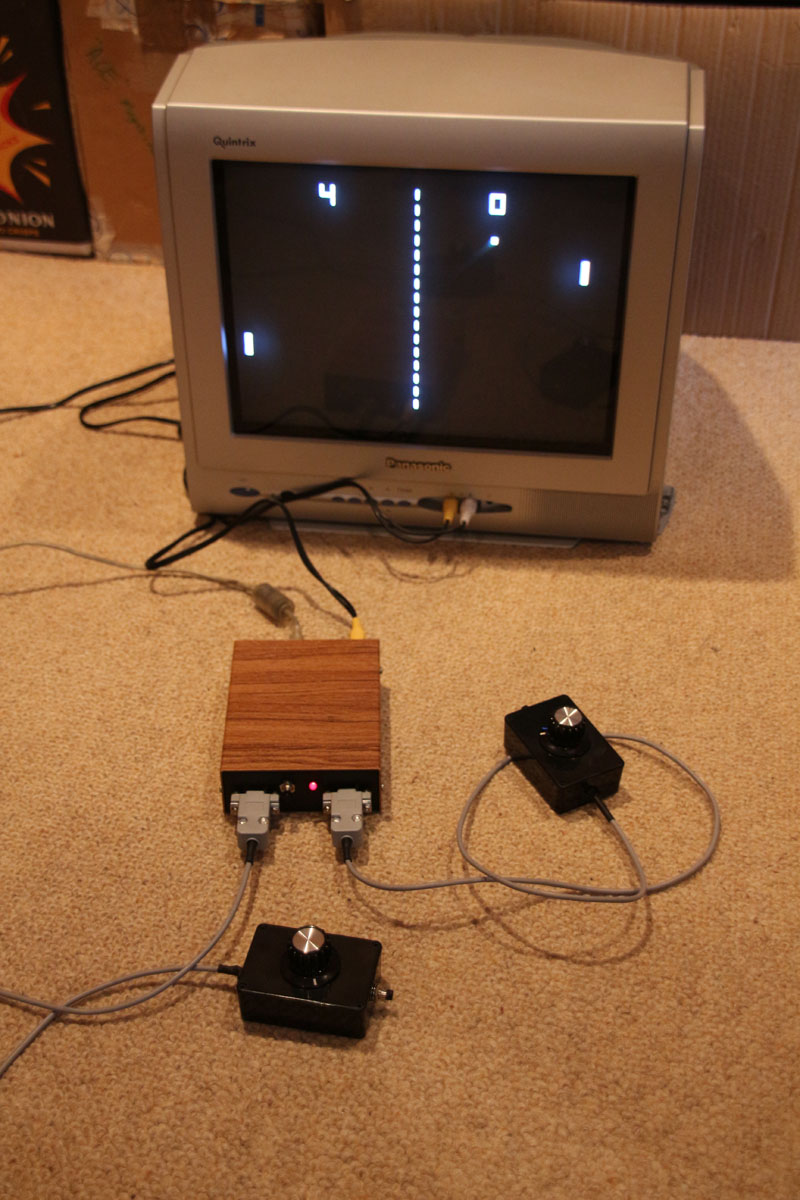
I always wanted to build my own games console, so I was pleased when I stumbled across the TVOut library for the Arduino. It enables many different types of Arduino to generate both video (PAL and NTSC) and audio signals using interrupts. One of the best things about the library is the minimal hardware that is required to implement it – just 2 resistors at its most basic.
Of course, I wasn’t surprised to find out that others had had the same idea, probably the best known of which is the Hackvision by nootropic design.
I wanted to build a system that allowed the external connection of 2 joystick or 2 paddle controllers, and the Hackvision *almost* meets these requirements; 2 paddles can be used, but it only allows for 1 joystick/d-pad. Now I could’ve just ignored the Hackvision, and built my own version, but the Hackvision has had some really good games written for it I wanted to be able to play. I needed a way to build something that could be used with 2 joysticks, but was still compatible with the Hackvision.
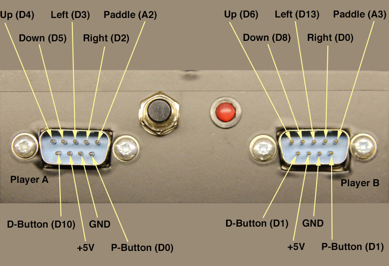
The Hackvision design does actually have unassigned IO pins, although not the 5 required to simply assign to the functions of a joystick. I found that I could *just* manage to connect everything if I reused pin D0 (which is used for the first paddle button) for a direction function on the second joystick, and used pin D1 for both the paddle button and joystick button on the second controllers (the first controllers use different pins for the paddle and joystick buttons).
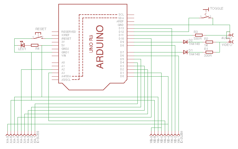
Confused?! The circuit and pinout should make things clearer:
Console circuit – basically an Arduino and a hand-full of passive components.Controller ports labelled with functions and associated Arduino pins
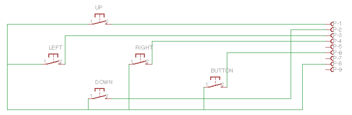
Sticking to the pinouts for Player A & B ports enables the use of classic joysticks with an “Atari” connector that were used throughout the 80s and 90s, and can still be sourced relatively easily on eBay, etc. If you really insist on making your own, then this is the circuit:
Joystick/D-Pad circuit
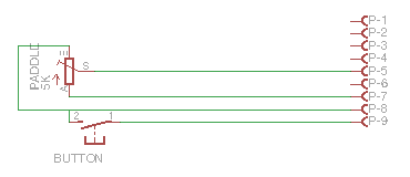
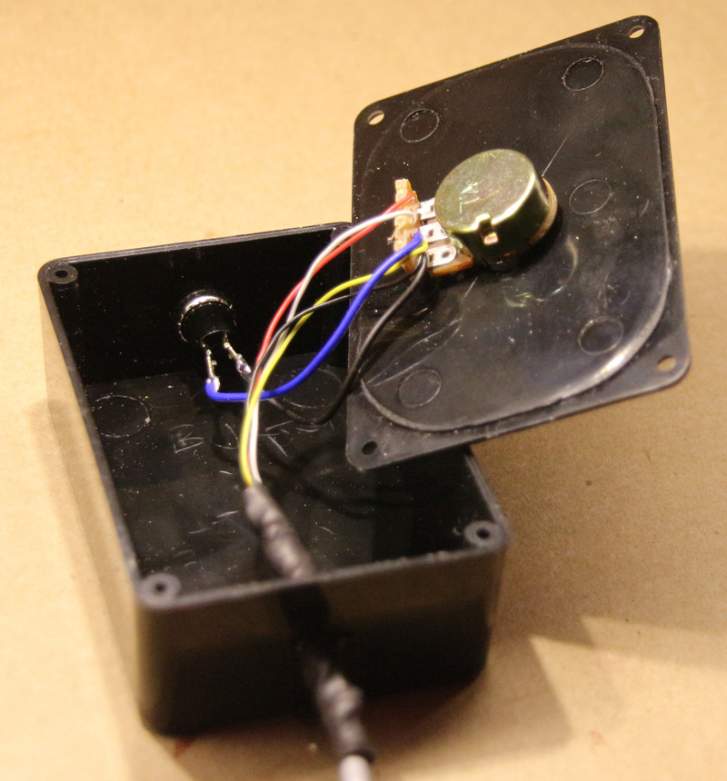
I’m afraid you’ll have to make your own paddle controllers, but they’re pretty simple:
Paddle circuitPaddle controller construction
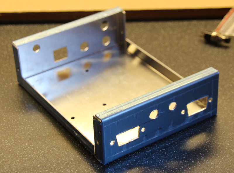
Housing a project in an enclosure is always more complicated and time consuming that you anticipate. I happened to have an aluminium project box in my parts-bin:
Prepared aluminium chassis
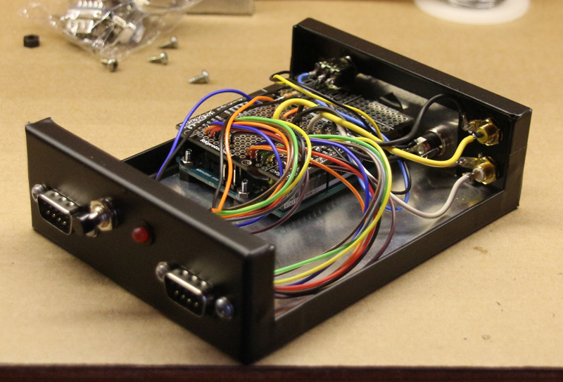
Sticky-backed plastic (Fablon) gives a good exterior finish, and is far-less hassle than painting:
Internal construction
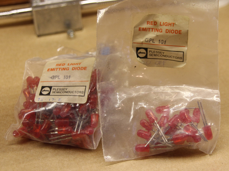
My grandfather used to work for Plessey back in the 70s – these LEDs found their way into his workshop…
Ancient LEDs
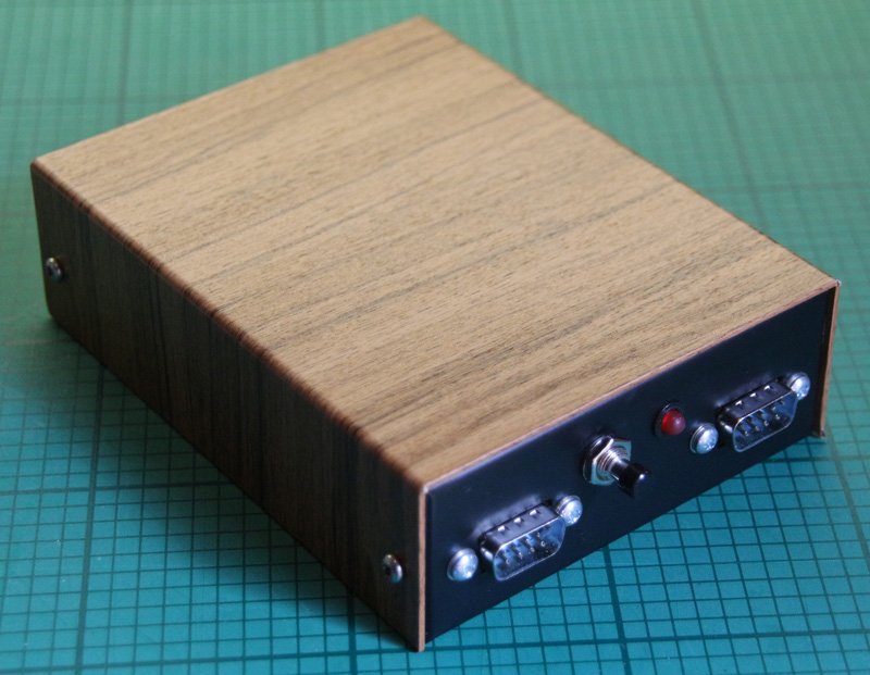
Woodgrain Fablon for the authentic ‘retro’ look:
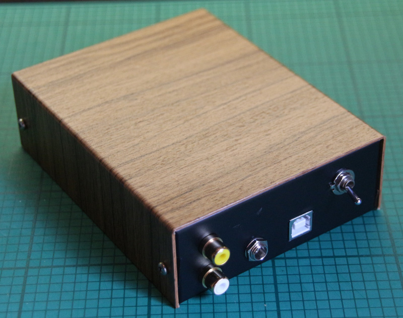
Finished console – Front
Finished console – Rear
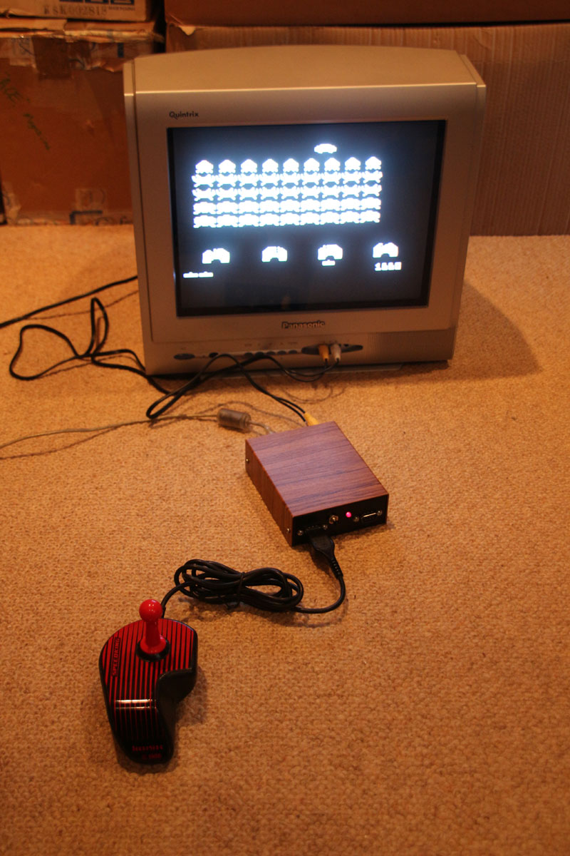
Hackvision Space Invaders
I intend to write a library for the console, however I’ll have to do that at a later date. Since upgrading my Mac to OSX ‘El Capitan’, the Arduino IDE is refusing to upload anything to any of my Arduinos. I’ll get around to it when I get it fixed.